2
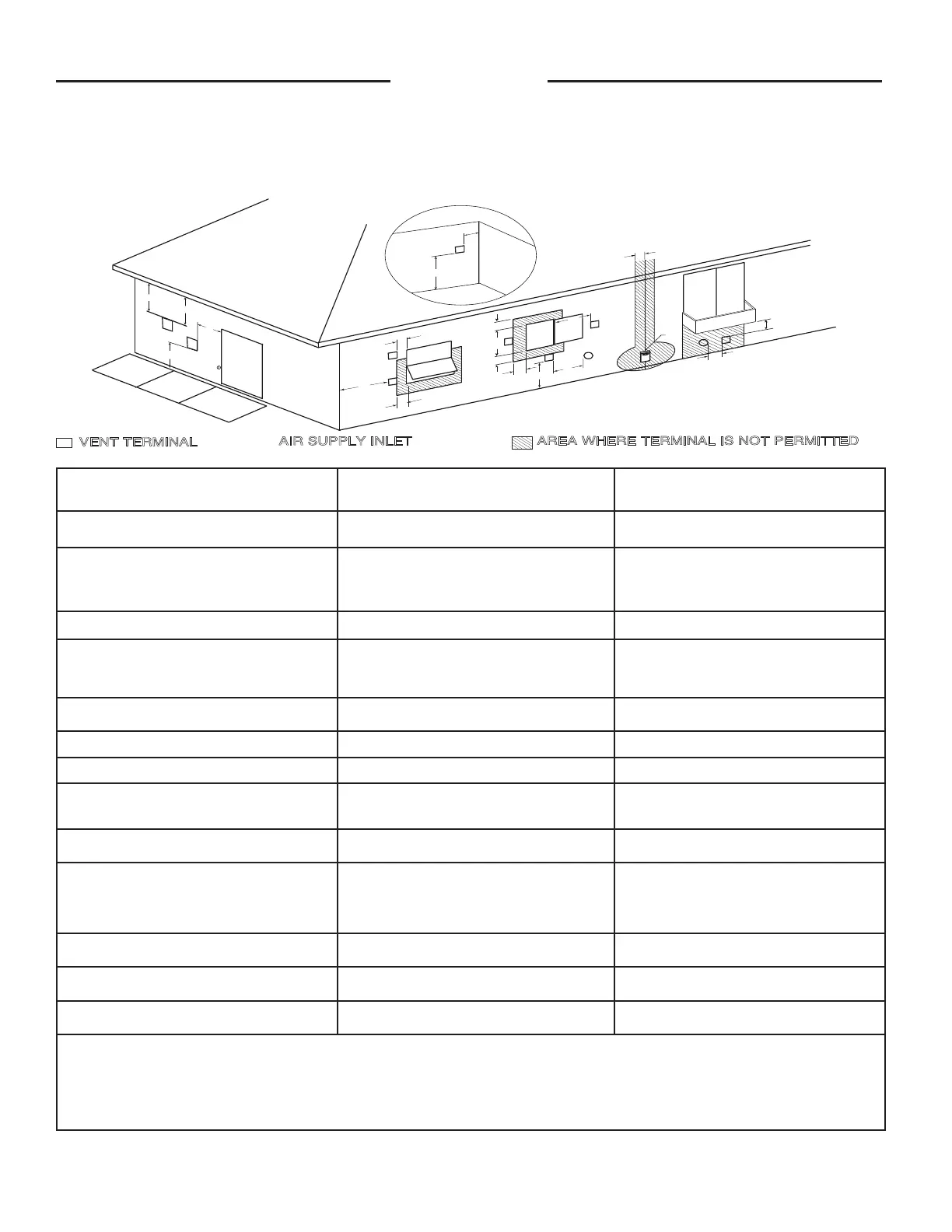
Water Heater Exhaust Terminal Location
The following information should be used for determining the proper location of the vent terminal for outdoor tankless
water heaters.
D
V
V
E
FI
X
E
D
C
L
O
S
E
D
O
P
E
R
A
B
L
E
O
P
E
R
A
B
L
E
F
I
X
E
D
C
L
O
S
E
D
v
v
B
L
F
C
B
v
v
v
X
B
B
B
A
J
C
I
H
X
v
M
K
v
G
A
V
VENT TERMINAL
X
A
IR SUPPLY INLET
AREA WHERE TERMINAL IS NOT PERMITTED
Canadian Installations
1
Indoor and Outdoor
US Installations
2
Outdoor
A= Clearance above grade, veranda, porch, deck or
balcony.
12 inches (30 cm) above anticipated snow level. 12 inches (30 cm) above anticipated snow level.
B= Clearance to window or door that may be
opened.
6 inches (15 cm) for appliances ≤ 10,000 Btuh (3
kW), 12 inches (30 cm) for appliances > 10,000
Btuh (3kW) and ≤100,000 Btuh (30kW), 36 inches
(91 cm) for appliances > 100,000 Btuh (30kW).
6 inches (15 cm) for appliances ≤ 10,000 Btuh (3
kW), 9 inches (23 cm) for appliances > 10,000
Btuh (3kW) and ≤ 50,000 Btuh (15kW), 12 inches
(30 cm) for appliances > 50,000 Btuh (15kW).
C= Clearance to permanently closed window.
* *
D= Vertical Clearance to ventilated soft located
above the terminal within a horizontal distance
of 2 feet (61 cm) from the center line of the
terminal.
* *
E= Clearance to unventilated soft.
* *
F= Clearance to outside corner.
* *
G= Clearance to corner.
* *
H = Clearance to each side of center line extended
meter/regulator assembly.
3 feet (91 cm) within a height 15 feet (4.57 m) above
the meter/regulator assembly.
*
I = Clearance to service regulator vent outlet. 3 feet (91 cm)
*
J = Clearance to nonmechanical air supply inlet to
building or the combustion air inlet to any other
appliance.
6 inches (15 cm) for appliances ≤10,000 Btuh (3
kW), 12 inches (30 cm) for appliances > 10,000
Btuh (3kW) and ≤ 100,000 Btuh (30kW), 36 inches
(91 cm) for appliances > 100,000 Btuh (30kW).
6 inches (15 cm) for appliances ≤10,000 Btuh (3
kW), 9 inches (23 cm) for appliances > 10,000
Btuh (3kW) and ≤ 50,000 Btuh (15kW), 12 inches
(30 cm) for
appliances > 50,000 Btuh (15kW)
K = Clearance to mechanical air supply inlet. 6 feet (1.83 m) 3 feet (91 cm) above if within 10 feet (3 m) hori-
zontally.
L = Clearance above paved sidewalk or paved drive-
way located on public property.
7 feet (2.13 m) *
M = Clearance under veranda, porch, deck or
balcony.
Not Allowed Not Allowed
1
In accordance with current CAN/CGA-B149 Installation Code
2
In accordance with current ANSI Z223.1/NFPA National Fuel Gas Code.
* If clearances are not specied, then follow local installation codes and the requirement of the gas supplier.
** For condensing appliances: The vent for this appliance shall not terminate over public walkways, near soft vents, crawl space vents, or other areas where conden-
sate or vapor could create a nuisance, hazard or cause property damage, or where condensate or vapor could cause damage or could be detrimental to the operation
of regulators, relief valves or other equipment.
Installation
 Loading...