18
!-*
'%-+,!'&!*!,,!&
-($'/ '/&$'/ '*!2'&,$
(.
'-$
$'/
,'(
'(,!'&
0 -+,
(.$'/
+!
'(,!'&
(.
'-$
$'/
'%-+,!'&!*
0 -+,
,, '-$$'/,'!&,#!*
'$$*&+-*/!, ,/'+ ,
%,$+*/+,'(*.&,!&,$
$'#'!&,#!*'(&!&
&',/ &-*&!+!&+,$$!&
'*!2'&,$('+!,!'&'&$1'&M
$'/!+*)-!*!&+,$$, $'/
+', '(&&!+('!&,'/&/*
,, '-$$'/,','(!&$,
!*'(&!&'*M$'/,'+!
!
&$,!*'(&!&,'(*.&,
!&,$$'#'!&,#
'(&!&($-'(&!&&',-+
I337 I336
Method 2
(Not Shown)
One permanent opening, located
within 12 inches of the top of the
e
nclosure, shall be permitted
w
here the equipment has
clearances of at least 1 inch from
the sides and back and 6 inches
from the front of the appliance.
The opening shall directly
communicate with the outdoors or
communicate through a vertical or
horizontal duct to the outdoors or
spaces (crawl or attic) that freely
c
ommunicate with the outdoors,
and shall have a minimum free
area of:
a. 1 square inch for each 3,000
BTUH of the total input rating of all
equipment located in the enclosure
and
B
TUH Free Area Round Pipe
I
nput Each Opening Size
4
5,000 15.00 square inches 4"
6
0,000 16.67 square inches 5"
7
5,000 25.00 square inches 6"
90,000 30.00 square inches 6"
105,000 35.00 square inches 7"
b. Not less than the sum of the
areas of all vent connectors in the
confined space.
If unit is installed where there is an
exhaust fan, sufficient ventilation
must be provided to prevent the
exhaust fan from creating a negative
pressure.
Combustion air openings must not be
restricted in any manner.
'&+-$,$'$'+'*
+(!$*)-!*%&,+
CONNECTION TO
FURNACE
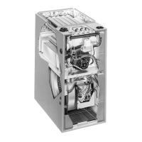
!%('*,&,When indoor
c
ombustion air is used, the inlet air
opening at the furnace must be
protected from accidental blockage.
On upflow models, install a 90° elbow
pointing downward in the side inlet air
opening or a double elbow pointing
downward in the top inlet air opening.
On downflow/horizontal models,
install a double elbow in the top inlet
a
ir opening. See Figure 14.
 Loading...