9
SITE SELECTION
1. Select a site in the building near
the center of the proposed, or
existing, duct system.
2. Give consideration to the vent
system piping when selecting the
furnace location. Be sure the
venting system can get from the
furnace to the termination with
minimal length and elbows.
3. Locate the furnace near the
existing gas piping. Or, if running
a new gas line, locate the
furnace to minimize the length
and elbows in the gas piping.
4. Locate the furnace to maintain
proper clearance to combustibles
as shown in the following tables.
'&',$!,, -&!,1,
,0 &*,-+
'!&+'&*#, ,
0 &*++%$1&
-+','*$+
!&,', &.!*'&%&,/ !
&*+-$,!&(*+'&$
!&"-*1'*,
!
/*&!&
'%-+,!$%,*!$%-+,
&',($'&'*!&+,
, -*&"#,,
**'-&, -*&
%-+,#(,$*&*
'$$'%-+,!$
%,*!$+!&$-!&
+'$!&&', *
$%%$.('*+&
$!)-!+($%&,'
'%-+,!$%,*!$+'&
!&+,'**'-&,
-*&"#,&-+
&0($'+!'&'*!*
*+-$,!&!&(*'(*,1
%(*+'&$!&"-*1'*
, , '%'/&*
+ '-$-,!'&, ,
, -*&*%-+,&',
-++*''%$'+,
'*'*&1', *+,'*
(-*('++
c. The heat tape should be rated
at 5 or 6 watts per foot at
1
20V.
!%('*,&,Support this unit
when installed. Since this furnace
is suitable for attic or crawl space
installation, it may be installed on
combustible wood flooring or by
using support brackets. +77
;9GD7
5. !%('*,&,!8;@EF3>>;@9;@3
GF;>;FKDAA?47EGD7F:76AAD
;EI;677@AG9:FA
a. allow the largest part of the
furnace to pass; or
b. allow any other appliance
(such as a water heater)
to pass.
6. !%('*,&,This furnace is not
approved or recommended for
installation on its back, with
access doors facing upwards.
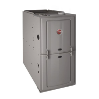
CLEARANCE -
ACCESSIBILITY
The design of forced air furnaces with
input ratings as listed in the tables
under Figures 6, 7, and 8 are certified
by CSA-International for the
clearances to combustible materials
shown in inches.
See name/rating plate and clearance
label for specific model number and
clearance information.
Service clearance of at least 24
inches is recommended in front of
all furnaces.
&',Use recommended 24”
clearance if accessibility clearances
are greater than fire protection
clearances.
-($'/& '*!2'&,$
-*&+*+!&
*,!!'*!&+,$$,!'&
'&'%-+,!$$''*+
&', '/.*, ,
-*&+%-+,&',
!&+,$$!*,$1'&
*(,!&,!$'*', *
'%-+,!$%,*!$', *
, &/''$''*!&
!&+,$$,!'&'&
'%-+,!$%,*!$&
*+-$,!&!*-+!&
(*'(*,1%(*+'&$
!&"-*1'*,
!-*
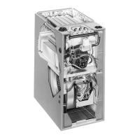
'*!2'&,$-*&!&+,$$/+-(('*,*#,+
!
/*&!&
-B8>AI8GD@357E3D7E:;BB76I;F:3
4AFFA?5>AEGD7B3@7>;@EF3>>76
/:7@4AFFA?D7FGD@3;D;EGE76
D7?AH7F:7B3@7>4KD7?AH;@9F:7
FIAE5D7IE3FF35:;@9F:7B3@7>FA
F:78DA@F43E73@9>7+77;9GD7
G
AS
P
IPE
T
RAP
E
XHAUST
F
AN
ELECTRICAL
CONDUIT
I
NTAKE
V
ENT
I522
!
/*&!&
 Loading...