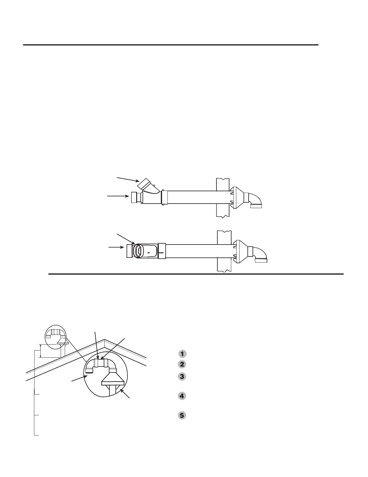
Horizontal Vent- Alternate Concentric, and Combustion Air-Inlet
Terminal Installation:
Contact Manufacturer's National Service Department for
Kit information, see If You Need Service section.
Determine the location for the concentric vent and com-
bustion air-inlet terminal then make a hole through the
exterior wall to accommodate the terminal (see Figure 5).
Insert the concentric vent and combustion air-inlet ter-
minal assembly through the wall as shown. Ensure that
the back of the supplied terminal is ush with the outside
wall surface.
Complete the installation of the remainder of the vent
system and attach it to the vent connector tting on the
water heater’s blower assembly. Horizontal lengths of
the vent system must slope downward away from the
water heater a minimum of 1/8 in. per foot (10 mm per
meter).
Complete the installation of the remainder of the combus-
tion air-inlet system and attach it to the combustion
air-inlet connector tting on the water heater’s combus-
tion air-inlet tube assembly. Horizontal lengths of the
combustion air-inlet system must slope downward away
from the water heater a minimum of 1/8 in. per foot (10
mm per meter). The terminal may be installed with the
Combustion Air-inlet Connection orientated in any posi-
tion from upward vertical (see Figure 5) to 90° horizontal
(see Figure 6). DO NOT install the terminal with the
Combustion Air-Inlet Connection angled downward.
Support vertical and horizontal lengths of the vent and
combustion air-inlet systems as previously mentioned.
Vent
Connections
Figure 5
Combustion Air-Inlet
Connection
Vent
Connections
Combustion Air-Inlet
Connection
Figure 6
NOTICE: All pipe, fittings, solvent cement, primers
and procedures must conform to American National
Standards Institute and American Society for Testing and
Materials (ANSI/ASTM) standards.
Vertical Vent - Alternate Concentric, and Combustion Air-Inlet Installation:
Contact Manufacturer's National Service Department for Kit information, see If You Need Service
section.
The location of the vent and combustion air-inlet terminals depends on
the following minimum clearances and considerations.
Minimum 12 in. (30.5 cm) above roof.
Minimum 12 in. (30.5 cm) above anticipated snow level.
Maximum 24 in. (61 cm) above roof level without additional
support for vent.
Four feet (1.22 m) from any gable, dormer or other roof struc-
ture with building interior access (i.e., vent, window, etc.).
Ten (10) ft. (3.05 m) from any forced air inlet to the building.
Any fresh or make-up air inlet such as a dryer or furnance area
is considered to be a forced air inlet.
18
Terminals with ½” Mesh Protective
Screen and Termination Restrictor
Inside. Note: Termination Restrictors
used on 75 Gallon models ONLY.
Concentric Vent and
Combustion Air-Inlet
Through Roof
Vent
Short Piece of Pipe
Min. 12 in. (30.5m) Above
Roof
Min. 12 in. (30.5m) Above
Above Anticipated Snow
Level
Max. 24 in. (61 cm) Above
Roof (Without Additional
Support)
Important: The vent terminal must not terminate below the
combustion air-inlet terminal.
21
 Loading...