4
INTRODUCTION TO YOUR FURNACE
Thank you for the purchase of your new modulating gas fur-
nace! This furnace is designed to be the ultimate in heating
comfort and is the only true modulating gas furnace available
on the market today.
The modulating gas furnace provides a superior level of
comfort due to the interaction of seven basic components:
•
Variable Output Thermostat - Whereas conventional ther-
mostats only send an On/Off signal to the furnace, the ther-
mostat for the modulating furnace system is specially
designed to indicate the exact heating requirements of the
conditioned space. This is accomplished by a logic control
routine that accurately senses the space load, minimizes
recovery times, reduces temperature swings and optimizes
system efficiency and performance.
• Fully Communicatiing Thermostat Modulating Gas Valve -
The gas valve has the conventional redundant solenoid
valves for inherent safety, but also has a third operator for
capacity control. This operator is actually a servo valve
which varies the input rate of the furnace proportionally to
the signal from the controller. The modulating furnace can
operate anywhere from 40% to 100% of the nameplate input
of the furnace.
•
Furnace Controller - The furnace controller provides all of
the ignition and safety functions of the typical IFC as well as
i
nterpreting the signals from the thermostat. The furnace
controller will optimize furnace performance by monitoring all
thermostat and temperature inputs and insuring the stable
operation of the inducer, gas valve and indoor blower motor.
• ECM Variable Speed Blower - The airflow through the duct
w
ork is varied to meet the load demand. Airflow as low as
300 CFM is achieved by the response of a brushless perma-
nent magnet variable speed blower motor.
• Two Speed Draft Inducer - To insure clean combustion
and peak efficiency, the induced draft motor speed is adjust-
e
d based on the gas valve setting to provide the proper
amount of combustion air to the burners.
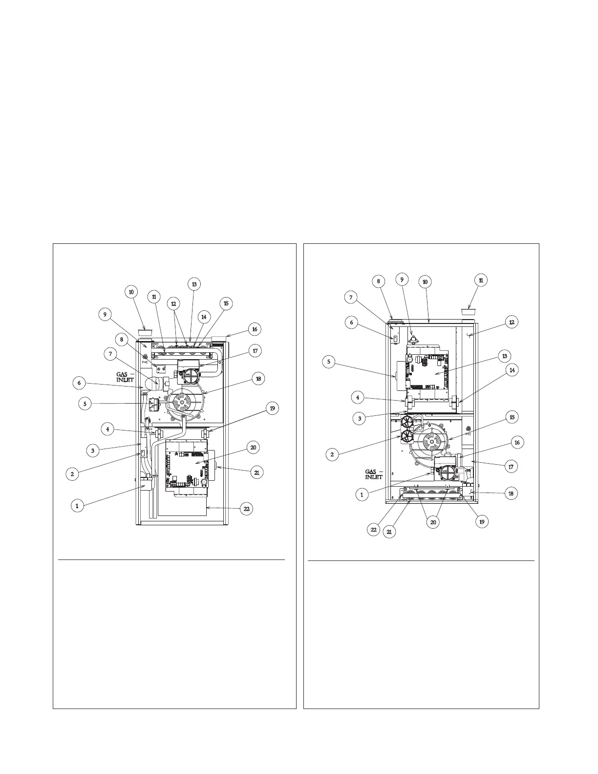
FIGURE 3
DOWNFLOW FURNACE
FIGURE 2
UPFLOW FURNACE
ST-A1123-01_01
ST-A1123-01_02
ITEM
NO. PART NAME
1 CONDENSATE TRAP
2 DOOR SWITCH
3 JUNCTION BOX
4 TRANSFORMER
5 PRESSURE SWITCH ASSEMBLY
6 EXHAUST TRANSITION
7 CONNECTOR
8 MAIN LIMIT
9 EXHAUST AIR PIPE
10 VENT CAP SHIPPING PLUG
11 FLAME SENSOR
12 OVERTEMPERATURE SWITCH
ITEM
NO. PART NAME
13 TOP PLATE
14 BURNER
15 IGNITER
16 COMBUSTION AIR INLET
17 GAS VALVE
18 INDUCED DRAFT BLOWER
19 POWER FACTOR CHOKE
20 INTEGRATED FURNACE CONTROL
21 BLOWER MOTOR
22 BLOWER HOUSING
ITEM
NO. PART NAME
1 GAS VALVE
2 PRESSURE SWITCH ASSEMBLY
3 BLOWER HOUSING
4 POWER FACTOR CHOKE
5 BLOWER MOTOR
6 DOOR SWITCH
7 JUNCTION BOX
8 COMBUSTION AIR INLET
9 HALC
10 TOP PLATE
11 VENT CAP SHIPPING PLUG
12 OUTLET AIR PIPE
ITEM
NO. PART NAME
13 INTEGRATED FURNACE CONTROL
14 TRANSFORMER
15 INDUCED DRAFT BLOWER
16 CONNECTOR
17 EXHAUST TRANSITION
18 CONDENSATE TRAP
19 IGNITER
20 OVERTEMPERATURE SWITCH
21 BURNER
22 FLAME SENSOR
 Loading...