32
F
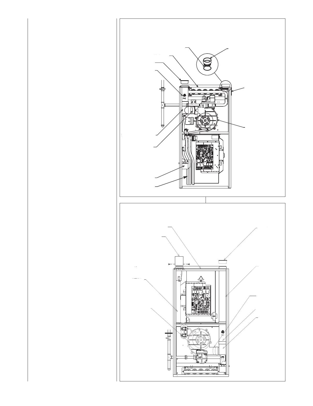
IGURE 27
U
PFLOW COMBUSTION AIR AND VENT PIPE CONNECTION
I
329
CONDENSATE TRAP
CONNECTOR
I
NDUCED DRAFT
BLOWER
P
LUG OPT. COMBUSTION
AIR POSITION
NOTE:
WHEN COMBUSTION AIR IS IN
O
PTIONAL POSITION SWAP LOCATION
OF 2" PVC MALE ADAPTER AND “O”
RING WITH PLUG.
EXHAUST TRANSITION
EXHAUST
OUTLET AIR PIPE
EXHAUST
VENT CAP/PLUG
TOP PLATE
“
O”RING
COMBUSTION
A
IR ADAPTER
DRAIN HOSES
(AS SHIPPED FROM
FACTORY)
CONNECTING TO FURNACE
IMPORTANT: Clean and debur all
pipe cuts. The shavings must not be
allowed to block the exhaust,
combustion air or condensate drain
pipes.
UPFLOW FURNACE
The exhaust pipe connection is a 2-in.
f
emale PVC pipe fitting extending
through the left side of the furnace top
plate. This opening has a protective
cap which should be removed just
prior to installing the exhaust pipe.
When 2-in. pipe is used, connect it
directly to this fitting. When 3-in. pipe
is used, connect a 2 to 3-in. coupling
to this fitting with a short piece of 2-in.
PVC pipe.
The combustion air connection
is at the right side of the top plate.
An alternate combustion air
connection may be made on the right
side of the jacket. This opening has a
plastic cap. A combustion air
connection fitting is supplied with the
furnace and it must be installed in the
furnace by screwing it into the
opening. Make sure the rubber
“O-ring” supplied with the furnace is
used with this fitting. See Figure 27.
DOWNFLOW/HORIZONTAL
FURNACE
The exhaust pipe connection is a 2-in.
female PVC pipe fitting extending
through the right side of the furnace
top cover. This opening has a pro-
tective cap which should be removed
just prior to installing the exhaust
pipe. When 3-in. pipe is used,
connect a 2 to 3-in. coupling to this
fitting with a short piece of 2-in. PVC
pipe.
The combustion air connection is a 2-
in. extruded hole on the left side of
the top plate. When a 2-in. pipe is
used, attach a 2-in. PVC coupling
over this hole with RTV sealant, drill
two pilot holes, and add two sheet
metal screws through the coupling
into the extrusion to secure it in place
before piping. When 3-in. pipe is
used, connect a 2 to 3-in. coupling to
this fitting with a short piece of 2-in.
PVC pipe. See Figure 28.
FIGURE 28
DOWNFLOW/HORIZONTAL COMBUSTION AIR AND VENT PIPE CONNECTION
EXHAUST VENT
CAP/PLUG
EXHAUST
PIPE - PVC
EXHAUST
CONNECTOR
EXHAUST
TRANSITION
TOP PLATE
COUPLING
COMBUSTION
AIR CHASE
EXHAUST
OUTLET AIR PIPE
a103101
NOTE:
ATTACH COUPLING TO
EXTRUDED COLLAR WITH
TWO SCREWS. PUT BEAD
OF SILICONE AROUND
BASE BEFORE
MOUNTING COUPLING.
INDUCED DRAFT
BLOWER
 Loading...