40
TABLE 8
LP GAS PIPE CAPACITY TABLE (CU. FT./HR.)
Maximum capacity of pipe in thousands of BTU per hour of undiluted liquefied petroleum gases (at 11 inches water
column inlet pressure).
(Based on a Pressure Drop of 0.5 Inch Water Column)
Nominal Length of Pipe, Feet
Iron Pipe
Size, Inches 10 20 30 40 50 60 70 80 90 100 125 150
1/2 275 189 152 129 114 103 96 89 83 78 69 63
3/4 567 393 315 267 237 217 196 182 173 162 146 132
1 1,071 732 590 504 448 409 378 346 322 307 275 252
1-1/4 2,205 1,496 1,212 1,039 913 834 771 724 677 630 567 511
1-1/2 3,307 2,299 1,858 1,559 1,417 1,275 1,181 1,086 1,023 976 866 787
2 6,221 4,331 3,465 2,992 2,646 2,394 2,205 2,047 1,921 1,811 1,606 1,496
Example (LP): Input BTU requirement of unit, 120,000
Equivalent length of pipe, 60 ft. = 3/4" IPS required.
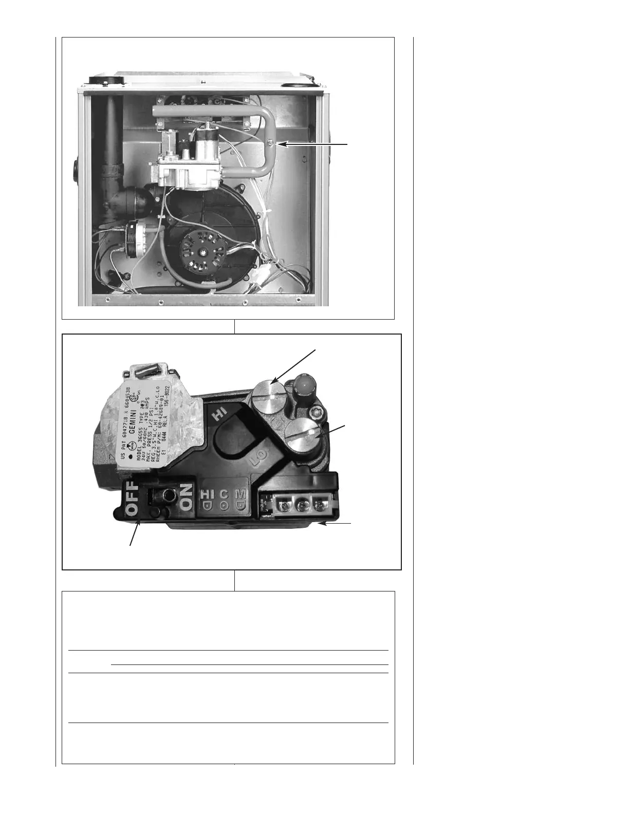
FIGURE 37
MANIFOLD PRESSURE TAP
Manifold Gas Pressure
Measurement. Natural gas
manifold pressure should be 3.5"
w.c.; LP gas manifold pressure
should be 10" w.c. Only small
variations on gas pressure should be
made by adjusting the pressure
regulator.
1. With the gas shut off at the
manual gas stop, remove the
pressure tap plug in the gas
manifold or the gas valve outlet.
See Figure 37.
2. Connect a U-Tube manometer to
this pressure tap. See Figure 39.
3. Turn on the gas supply and
operate the furnace in high heat
mode.
4. Note or adjust the manifold gas
pressure to give:
A. 3.5" w.c. for natural gas high
fire.
B. 10" w.c. for LP gas high fire.
5. To adjust the pressure regulator
for high fire, remove the regulator
cap located on the side of the
regulator. See Figure 38.
6. Turn the adjustment screw
clockwise to increase pressure or
counterclockwise to decrease
pressure.
7. Securely replace the regulator
cap for high fire.
8. Operate the furnace in low
speed.
9. Note or adjust the manifold
pressure to give:
A. 1.7" w.c. for natural gas low
fire.
B. 4.8" w.c. for LP gas low fire.
10. To adjust the pressure regulator
for low fire, remove the regulator
cap on the top of the regulator.
See Figure 38.
11. Turn the adjustment screw
clockwise to increase pressure or
counterclockwise to decrease
pressure.
12. Securely replace the regulator
cap for low fire.
13. Verify pressures for high and low
fire operation.
14. Shut off gas at the manual gas
valve and remove the U-Tube
manometer.
15. Replace the manifold pressure
tap plug before turning on gas.
Check for leak.
MANIFOLD
PRESSURE
TAP
FIGURE 38
TYPICAL GAS VALVE
INLET
PRESSURE TAP
OUTLET
PRESSURE
TAP
HIGH FIRE
MANIFOLD
PRESSURE
ADJUSTMENT
LOW FIRE
PRESSURE
MANIFOLD
ADJUSTMENT
 Loading...