EasyManua.ls Logo

Rheem RQPM 15/16 Seer Series User Manual

Rheem RQPM 15/16 Seer Series
52 pages
To Next Page IconTo Next Page
Page #1 background imageLoading...
Page #1 background image
[ ] INDICATES METRIC CONVERSION
INSTALLATION INSTRUCTIONS
PACKAGE HEAT PUMPS FEATURING
INDUSTRY STANDARD R-410A
REFRIGERANT
RQRM 15/16 SEER SERIES (2
1
2
, 3, 4 TONS
RQPM 14 SEER SERIES (2 - 5 TONS)
RQNM 13 SEER SERIES (2 - 5 TONS)
92-20522-47-08
SUPERSEDES 92-20522-47-07
RECOGNIZE THIS SYMBOL AS AN INDICATION OF IMPORT TION!
!
DO NOT DESTROY THIS MANUAL
PLEASE READ CAREFULLY AND KEEP IN A SAFE PLACE FOR FUTURE REFERENCE BY A SERVICEMAN
WARNING
!
ANT SAFETY INFORMA
THESE INSTRUCTIONS ARE INTENDED AS AN AID TO
QUALIFIED, LICENSED SERVICE PERSONNEL FOR PROPER
INSTALLAT ION, ADJUSTMENT AND OPERATION OF THIS
UNIT. READ THESE INSTRUCTIONS THOROUGHLY BEFORE
AT TEMPTING INSTALLATION OR OPERATION. FAILURE TO
FOLLOW THESE INSTRUCTIONS MAY RESULT IN IMPROPER
INSTALLAT ION, ADJUSTMENT, SERVICE OR MAINTENANCE
POSSIBLY RESULTING IN FIRE, ELECTRICAL SHOCK,
PROPERTY DAMAGE, PERSONAL INJURY OR DEATH.
ISO 9001:2008
Question and Answer IconNeed help?

Do you have a question about the Rheem RQPM 15/16 Seer Series and is the answer not in the manual?

Rheem RQPM 15/16 Seer Series Specifications

General IconGeneral
BrandRheem
ModelRQPM 15/16 Seer Series
CategoryHeat Pump
LanguageEnglish

Summary

Safety Information

General Installation Safety

Warnings about following instructions and using authorized components.

Electrical Safety Precautions

Mandatory warnings for power disconnection, grounding, and wiring.

Health and Environmental Warnings

Information on fiberglass insulation and Proposition 65.

Introduction

R-410A Refrigerant Details

Specifications, quick reference, coil/TXV, and required tools for R-410A.

Installation Procedures

General Installation Guidelines

Covers pre-installation checks and unit location.

Pre-Installation Check Points

Ensures structural integrity, clearances, power supply, and duct/drain provisions are met.

Unit Location Considerations

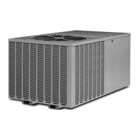
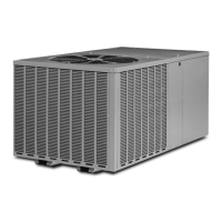
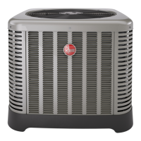
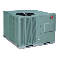
Details on outdoor installation, slab/rooftop placement, and airflow clearance.

Outside Slab Installation

Steps and considerations for installing the unit on an outdoor slab.

Clearance Requirements

Minimum clearances for unit performance and serviceability.

Rooftop Installation Guidelines

Ensures roof strength, level platform, and proper access for rooftop units.

Ductwork Installation

Ductwork Fabrication and Sizing

Guidelines for ductwork fabrication, sizing, and installation.

Filters

Filter Requirements and Installation

Details on field-installed filters for return air duct.

Condensate Drain System

Indoor Coil Condensate Drain

Instructions for connecting and maintaining the indoor coil drain.

Outdoor Coil Condensate Management

Outdoor Coil Condensate Management

Describes outdoor coil water runoff during heating and defrost cycles.

Electrical Wiring and Grounding

Power Wiring Requirements

Guidelines for branch circuit wiring, disconnects, and wire sizing.

Power Wiring and Heater Kit Installation

Instructions for connecting power to the unit and electric heater kit.

Control Wiring (Class II)

Guidelines for low voltage wiring and thermostat compatibility.

Internal Wiring Replacement

Instructions for replacing internal wiring with identical components.

Unit Grounding Procedure

Emphasizes permanent grounding for electrical safety.

Thermostat Installation

Thermostat Mounting and Wiring

Guidance on thermostat placement and connection.

Indoor Airflow Data

Blower Performance Data

Information on multi-speed indoor blower motor performance.

Pre-Start and Startup Procedures

Installation Pre-Start Inspection

Checks for proper location, level, wiring, grounding, and airflow.

Unit Startup Sequence

Steps for turning on power and verifying unit operation.

Unit Operation

Normal Operation and Controls

Details compressor behavior, overload protection, and time delay control.

Auxiliary Heat System

Auxiliary Heat Control and Application

Guidance on auxiliary heat requirements and system control.

Defrost and Pressure Controls

Demand Defrost Control

Monitors ambient temp, coil temp, and run-time for defrost cycles.

High/Low Pressure Controls

Provides active protection and system lockout based on pressure.

Enhanced Defrost Control Diagnostics

Diagnostic Codes and LED Indicators

Explains LED status for troubleshooting defrost control issues.

Related product manuals