EasyManua.ls Logo

Rheem RQMP 14 Series User Manual

Rheem RQMP 14 Series
40 pages
To Next Page IconTo Next Page
Page #1 background imageLoading...
Page #1 background image
[ ] INDICATES METRIC CONVERSION
INSTALLATION INSTRUCTIONS
PACKAGE HEAT PUMPS FEATURING EARTH-
FRIENDLY R-410A REFRIGERANT
RQPM 14 SEER SERIES (2 - 5 TONS)
RQNM 13 SEER SERIES (2 - 5 TONS)
92-20522-47-04
SUPERSEDES 92-20522-47-03
refrigerant
RECOGNIZE THIS SYMBOL AS AN INDICATION OF IMPORT TION!
!
DO NOT DESTROY THIS MANUAL
PLEASE READ CAREFULLY AND KEEP IN A SAFE PLACE FOR FUTURE REFERENCE BY A SERVICEMAN
WARNING
!
ANT SAFETY INFORMA
THESE INSTRUCTIONS ARE INTENDED AS AN AID TO
QUALIFIED, LICENSED SERVICE PERSONNEL FOR PROPER
INSTALLAT ION, ADJUSTMENT AND OPERATION OF THIS
UNIT. READ THESE INSTRUCTIONS THOROUGHLY BEFORE
AT TEMPTING INSTALLATION OR OPERATION. FAILURE TO
FOLLOW THESE INSTRUCTIONS MAY RESULT IN IMPROPER
INSTALLAT ION, ADJUSTMENT, SERVICE OR MAINTENANCE
POSSIBLY RESULTING IN FIRE, ELECTRICAL SHOCK,
PROPERTY DAMAGE, PERSONAL INJURY OR DEATH.
(14 SEER
MODELS ONLY)
Question and Answer IconNeed help?

Do you have a question about the Rheem RQMP 14 Series and is the answer not in the manual?

Rheem RQMP 14 Series Specifications

General IconGeneral
BrandRheem
ModelRQMP 14 Series
CategoryHeat Pump
LanguageEnglish

Summary

I. SAFETY INFORMATION

General Safety Warnings

Crucial safety alerts regarding installation, operation, and potential hazards.

II. INTRODUCTION

R-410A Refrigerant Information

Details on R-410A refrigerant specifications, handling, and required tools.

III. CHECKING PRODUCT RECEIVED

IV. EQUIPMENT PROTECTION FROM THE ENVIRONMENT

Environmental Protection and Maintenance

Guidance on protecting the unit from corrosive elements and recommended cleaning practices.

V. SPECIFICATIONS

VI. INSTALLATION - GENERAL CONSIDERATIONS

Pre-Installation Check-Points

Key points to consider before commencing installation, including structural and site readiness.

Unit Location Guidelines

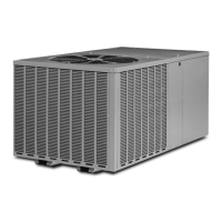
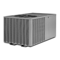
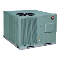
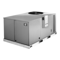
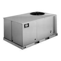
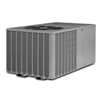
Recommendations for proper outdoor unit placement to ensure performance and minimize noise.

VI. INSTALLATION - OUTSIDE SLAB

VI. INSTALLATION - CLEARANCES

VI. INSTALLATION - ROOFTOP

VII. DUCTWORK

Ductwork Installation and Safety

Guidelines for fabricating and installing ductwork, including safety warnings.

VIII. FILTERS

IX. CONDENSATE DRAIN

X. CONDENSATE DRAIN, OUTDOOR COIL

XI. ELECTRICAL WIRING

Power Wiring Requirements

Guidelines for connecting the main power supply, including voltage and circuit requirements.

Electric Heater Kit Wiring

Step-by-step instructions for wiring the electric heater kit accessory.

XI. ELECTRICAL WIRING

Control Wiring (Class II)

Instructions for routing and connecting low voltage control wiring, including thermostat compatibility.

Internal Wiring

Guidance on internal wiring, including wire gauge and insulation replacement standards.

Grounding Requirements

Critical information on the necessity of permanent unit grounding for safety.

XI. ELECTRICAL WIRING

Thermostat Installation

Recommendations for thermostat mounting location and wiring compatibility.

XII. INDOOR AIR FLOW DATA

XIII. PRE-START CHECK

XIV. STARTUP

XV. OPERATION

XVI. AUXILIARY HEAT

Auxiliary Heat System and Safety

Information on auxiliary heat requirements, installation benefits, and safety warnings for heater kits.

Control System Operation Modes

Explanation of how the control system manages heating and cooling modes with the thermostat.

XVII. DEMAND DEFROST CONTROL

Defrost Initiation Conditions

Criteria that trigger the defrost cycle based on ambient and coil temperatures.

Defrost Termination Criteria

Conditions that stop the defrost cycle, including time and temperature limits.

Temperature Sensors and Test Mode

Details on temperature sensors and how to use the test mode for defrost control verification.

Troubleshooting Demand Defrost

Steps to diagnose and resolve issues related to the demand defrost control system.

XVIII. GENERAL DATA - RQPM Series

GENERAL DATA - RQNM Series

XIX. MISCELLANEOUS - Electrical and Physical Data

INDOOR AIRFLOW PERFORMANCE

ELECTRIC HEATER KIT – 1 PHASE RQNM

ELECTRIC HEATER KIT – 3 PHASE RQNM

FIGURE 7 WIRING DIAGRAM - RQNM SERIES

RQNM Series Wiring Information

Key wiring information, component codes, and wire color codes for RQNM series.

FIGURE 8 WIRING DIAGRAM - RQNM SERIES

RQNM Series Wiring Information

Detailed wiring diagram information, component codes, and wire color codes for RQNM series.

FIGURE 9 WIRING DIAGRAM - RQPM SERIES

RQPM Series Wiring Information

Wiring diagram, component codes, and wire color codes for RQPM series units.

FIGURE 10 WIRING DIAGRAM - RQPM SERIES

RQPM Series Wiring Information

Detailed wiring diagram, component codes, and wire color codes for RQPM series units.

FIGURE 11 CHARGING CHART

FIGURE 12 CHARGING CHART

FIGURE 13 CHARGING CHART

FIGURE 14 CHARGING CHART

FIGURE 15 CHARGING CHART

FIGURE 16 CHARGING CHART

Related product manuals