of times consecutively, pause and then repeat the process. To identify a Flash
Code number, count the number of consecutive flashes.
IMPORTANT: Every time the module powers up, the last ALERT Flash Code that
occurred prior to shut down is displayed for one minute. The module will continue to
display the flash code until the condition returns to normal or if 24VAC power is
removed from the module.
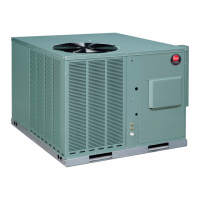
The control box cover allows access to the Comfort Alert™ status LEDs. An abbre-
viated Comfort Alert™ diagnostic chart is provided on the control box cover.
2. High Pressure Control (HPC)
The high pressure control (HPC) keeps the compressor from operating in pressure
ranges, which can cause damage to the compressor. This is an auto-reset control that
opens near 610 PSIG and closes once the system pressure drops below 420 PSIG.
The high pressure control is wired in the 24VAC side of the control circuitry.
3. Low Pressure Control (LPC)
The low pressure control (LPC) keeps the compressor from operating in pressure
ranges that can cause damage to the compressor. This is an auto-reset control that
opens near 90 PSIG and closes once the system pressure rises above 135 PSIG.
The low pressure control is wired in the common side of the control circuitry.
4. Comfort Alert With Active Protection
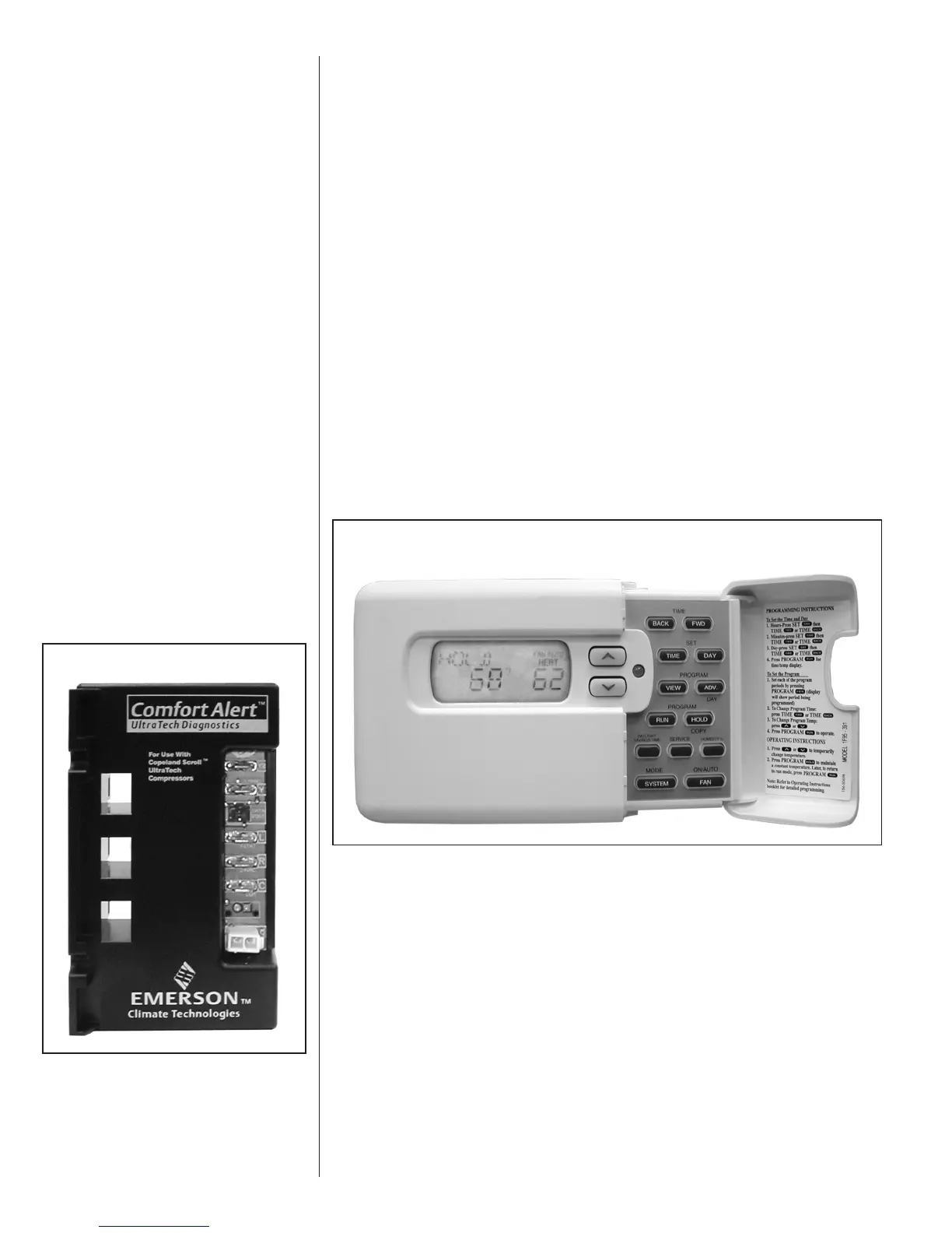
A two-stage cooling thermostat is required for proper unit operation.
Manufacturer recommends the use of thermostats that provide active compressor pro-
tection via the L terminal when the Comfort-Alert module on the unit is connected to the
L terminal on the thermostat.
FIGURE 2
WHITE-RODGERS 90-SERIES THERMOSTAT
FIGURE 3
8
 Loading...
