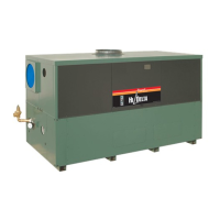
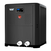
Do you have a question about the Rheem Raypak 2450 and is the answer not in the manual?
Explains hazard symbols and warning terminology used in the manual for safety.
Provides a general overview of the heat pump heater and encourages unit registration for warranty.
Specifies recommended chemical balance levels for pool and spa water to protect equipment.
Details requirements for unit placement, clearances, and avoiding obstructions for optimal operation.
Provides instructions and diagrams for securing the unit against high winds.
Details electrical power needs, breaker sizing, wire gauge, and connection guidelines.
Explains inlet/outlet connections, pipe types, and the necessity of shutoff/diverter valves.
Provides a table showing pressure drop across the heater for various flow rates.
Describes the LCD display, buttons (MENU/SET, UP, DOWN), and their functions for operation.
Guides on choosing and modifying modes like Pool Heat, Spa, Timed Spa, Pool Cool, and Pool Auto.
Explains how to enter and navigate the User and Installer/Service menus for configuration.
Provides detailed settings within the User Menu for time, display units, temperature limits, and pump periods.
Explains how to set the current time, C/F display, maximum spa, and maximum pool temperatures.
Details installer settings for Heat Only models and advanced parameters like voltage and sensor readings.
Outlines installer settings for Power Defrost and Heat/Cool models, including pump and valve configurations.
Explains how the control manages heating and cooling based on setpoints and ambient conditions.
Details pump control, low ambient lockout, control lock box, and auxiliary output modes.
Covers remote pool operation, specific pool/spa modes, and defrost functions.
Explains how to access fault history, run hours, and compressor start/run time settings.
Covers 3-way valve control, battery backup, and high water temperature limit.
Explains the lockout condition triggered by the high pressure switch and reset procedures.
Describes the lockout condition from the low pressure switch and its reset mechanism.
Details how the water pressure switch monitors flow and affects unit operation and valve switching.
Outlines the sequence from power application to normal operation, including setpoint reading and model type selection.
Explains how to increase/decrease desired water temperature for pool and spa modes.
Guides on changing the temperature display from Fahrenheit to Celsius or vice versa.
Describes the unit's capability for both heating and cooling the pool water.
Outlines steps to verify the control board, pump operation, and discharge air temperature upon initial start-up.
Provides steps for preparing the unit at the beginning of a heating season or for annual checks.
Details steps to secure and protect the unit if it will not be used during summer months.
Explains how to drain the water circuit to prevent damage from freezing conditions.
Outlines recommended periodic maintenance for reliability and performance, including coil cleaning.
Provides troubleshooting steps for when the unit is on but not heating the water effectively.
Guides users on diagnosing why the unit is not operating, checking breakers and settings.
Addresses potential condensation problems and how to distinguish them from leaks.
Explains common status messages displayed by the unit during operation and their meaning.
Lists error messages, their descriptions, and recommended troubleshooting steps.
Lists checks for power supply, water flow, and time clock before calling for service.
Explains how to reset the control board to factory default settings.
Provides steps for removing the control panel and junction box for service access.
Illustrates the recommended plumbing layout for systems without an external bypass.
Shows the plumbing diagram for systems requiring an external bypass valve.
Presents a general piping diagram with key components and important installation notes.
Illustrates piping configurations for multiple heat pumps in a primary/secondary setup.
Provides the detailed wiring diagram for single-phase digital models, including component labels and legends.
Guides on installing 2-wire controllers for "Chill" mode (Heat/Cool models only).
Details the installation process for 3-wire controllers for remote heating and cooling control.
Lists resistance values for 10K and 100K sensors at various temperatures for diagnostics.
Shows an exploded view of the unit with callouts for parts identification for specific models.
Provides a detailed table listing parts and their part numbers for models 2450-4450.
Shows an exploded view of the unit with callouts for parts identification for specific models.
Provides a detailed table listing parts and their part numbers for models 5450-8450.


 Loading...