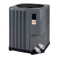
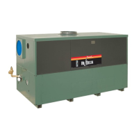
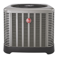
Do you have a question about the Rheem Raypak CROSSWIND V Series and is the answer not in the manual?
Information on safe installation distances and operational clearances for the unit.
Details on water connections, flow rate, and plumbing diagrams for system integration.
Guidelines for maintaining balanced water chemistry for optimal pool and spa operation.
Information regarding electrical connections and system power requirements.
Overview of the heater's control panel, display, and interface elements.
Explains hazard symbols and provides critical safety precautions for operation and usage.
Guidance on choosing a location and mounting the heater for optimal performance and safety.
Wiring schematic for single-phase heat only and heat/cool models.
Explanation of the Mode key's function for selecting operational modes.
Functionality of UP and DOWN keys for adjusting temperature setpoints.
Details on heating the pool or spa to the setpoint temperature.
How to set a specific duration for spa heating operation.
Functionality for cooling the pool in heat/cool models.
Automatic heating and cooling control for pool in heat/cool models.
Reviewing a log of past operational faults and error messages.
Displays compressor run time and the number of operational cycles.
Option to set the display language for menus and messages.
Resets all programmable settings to the manufacturer's default values.
Clears the historical fault log from the service menu.
Clears stored Wi-Fi network credentials for reconfiguration.
Selects the unit of temperature measurement (Fahrenheit or Celsius).
Sets the maximum allowable temperature for spa operation.
Sets the maximum allowable temperature for pool operation.
Configures the temperature range for cooling cycles in auto mode.
Defines the pool operation mode when using a remote selector.
Sets the temperature threshold for initiating a defrost cycle.
Determines when the defrost cycle ends based on coil temperature.
Sets the ambient temperature at which the unit will lock out operation.
Configures the unit's behavior during low voltage conditions.
Access to advanced settings for installation and external device configuration.
Access to configure the built-in scheduler for external devices.
Sets the operation mode for auxiliary relays controlling external devices.
Configures how the single-speed pump output is controlled.
Configures control for variable-speed pumps via digital outputs or Raypak Protégé.
Manages the operation mode for 3-way valve actuators.
How the control integrates with and manages a solar heater system.
Sets the heater's internal clock for scheduling functions.
Automatic clock synchronization when connected to Wi-Fi via Raymote.
Outlines the steps from initial power-up to ready-for-operation.
Procedures for safely starting the heater and verifying operation.
Displays and conditions for various operational messages like Heating, Cooling, No Demand.
Lists potential error messages and their corresponding troubleshooting steps.
Steps to enable or disable the remote operation mode.
Wiring guidelines for connecting remote control systems to the heater.
Steps to drain the water circuit for freeze protection.
How to clean the evaporator coil for efficient operation.
Basic instructions for cleaning the unit's exterior cabinet.
Checks and maintenance for condensation drain holes to prevent issues.
Checks to perform when the unit runs but does not heat the water.
Troubleshooting steps for when the unit fails to start or operate.
Steps to determine if excessive condensation indicates a leak.
Resetting control settings to factory defaults when programming is disarranged.
Procedures for safely accessing internal components for service.
Diagram for systems not requiring an external bypass.
Diagram showing the installation with an external bypass assembly.
Recommended piping configuration for a single heat pump unit.
Resistance values for the 100K inlet water temperature sensor.
Resistance values for 10K sensors used for outlet, ambient, and coil temperatures.
Instructions for downloading the app and creating a user account.
Steps to put the heater into connection mode.
Process for adding the heater to the Raymote app after connection.
Configuring the heater's name, location, and other profile details in the app.
Managing user profiles, app preferences, and organization settings.
Procedures for re-establishing Wi-Fi connection after reset or network changes.
Diagram showing the layout and function of external control terminal connections.
Wiring details for controlling a single-speed pump via a relay.
Connecting Raypak Protégé variable-speed pumps using the RS-485 Modbus harness.
Key considerations for running low-voltage control wiring safely.
Instructions for connecting an external safety input like an emergency stop button.
How the control integrates with and manages a solar heater system.
Steps for wiring the water flow switch to the heater control board.
| Category | Heat Pump |
|---|---|
| Brand | Rheem Raypak |
| Series | CROSSWIND V Series |
| Voltage | 208-230V |
| Phase | Single |
| Sound Level | 58 dB |
| Refrigerant | R410A |


 Loading...