EasyManua.ls Logo

Rheem RA17 Series - User Manual

Rheem RA17 Series
56 pages
Print Icon
To Next Page IconTo Next Page
Loading...
AIR COOLED
CONDENSING UNITS
92-104921-07-06 (4/18)
Printed in USA
[ ] indicates metric conversions.
Do not destroy this manual.
Please read carefully
and keep in a safe place
for future reference by a
serviceman.
WARNING
THESE INSTRUCTIONS
ARE INTENDED AS AN AID
TO QUALIFIED, LICENSED
SERVICE PERSONNEL FOR
PROPER INSTALLATION,
ADJUSTMENT, AND
OPERATION OF THIS
UNIT. READ THESE
INSTRUCTIONS
THOROUGHLY
BEFORE ATTEMPTING
INSTALLATION OR
OPERATION. FAILURE
TO FOLLOW THESE
INSTRUCTIONS MAY
RESULT IN IMPROPER
INSTALLATION,
ADJUSTMENT, SERVICE,
OR MAINTENANCE
POSSIBLY RESULTING IN
FIRE, ELECTRICAL SHOCK,
PROPERTY DAMAGE,
PERSONAL INJURY, OR
DEATH.
INSTALLATION INSTRUCTIONS
RA17 MODEL SERIES 17 SEER
WARNING:
RECOGNIZE THIS SYMBOL
AS AN INDICATION OF
IMPORTANT SAFETY
INFORMATION
FEATURING INDUSTRY STANDARD
R-410A REFRIGERANT

Table of Contents

Questions and Answers

  • S
    Sarah VasquezAug 17, 2025
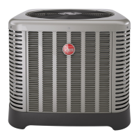
    What to do if my Rheem Heat Pump unit will not run?
    • M
      Mariah WardAug 17, 2025
      If your Rheem Heat Pump unit isn't running, several factors could be at play. Start by checking for correct voltage at the line voltage connections in the condensing unit. Also, make sure that the thermostat isn't out of calibration or set too high. Inspect the control board diagnostic codes. Look for blown fuses or tripped breakers and replace/reset them as needed. Check the transformer wiring and replace the transformer if it's defective. Reset the high-pressure control if it's open, and also refer to the high head pressure remedy. Do the same for the low-pressure control. Finally, verify the communication wiring if there's miswiring or the communication light is continuously on.
  • K
    katrinamartinAug 19, 2025
    Why is my Rheem RA17 compressor short cycling?
    • E
      Erica LewisAug 19, 2025
      If your Rheem Heat Pump's compressor is short cycling, it could be due to several reasons. First, check the voltage at the compressor terminals to ensure it's within ±10% of the nameplate marking when the unit is operating. A defective overload protector could also be the culprit, so consider replacing it. Finally, refrigerant undercharge can cause short cycling, so adding refrigerant may solve the issue.
  • C
    Carrie HuertaAug 22, 2025
    What causes insufficient cooling in my Rheem RA17 Heat Pump?
    • A
      Amy MyersAug 22, 2025
      Insufficient cooling in your Rheem Heat Pump can stem from several causes. The unit might be improperly sized, requiring a recalculation of the load. Improper indoor airflow could be the issue; it should be approximately 400 CFM per ton. An incorrect refrigerant charge can also lead to this problem, so charge the unit per the procedure attached to the service panel. Air, non-condensables, or moisture in the system necessitate recovering the refrigerant, evacuating, and recharging, along with adding a filter drier. A bad ID could also be the cause, in which case it should be replaced.
  • L
    Larry LeachAug 25, 2025
    Why is my Rheem Heat Pump's outdoor fan running, but the compressor isn't?
    • K
      kristenswansonAug 26, 2025
      If the outdoor fan is running but the compressor isn't in your Rheem Heat Pump, it could be due to a defective run or start capacitor, which would need replacement. Another possibility is a defective contactor, which should also be replaced. Check for correct voltage at the compressor and ensure all connections are secure. If the compressor is stuck, grounded, has an open motor winding, or an open internal overload, wait at least 3 hours for the overload to reset; if it remains open, replace the compressor. A low-voltage condition might also be the cause, in which case you should add start kit components.
  • A
    Anthony StoutAug 28, 2025
    What causes high head and high or normal vapor pressure in cooling mode on my Rheem RA17 Heat Pump?
    • S
      Sarah GardnerAug 28, 2025
      High head pressure along with high or normal vapor pressure in cooling mode on your Rheem Heat Pump can be attributed to a dirty outdoor coil, which needs cleaning. It could also be due to refrigerant overcharge, requiring a correction of the system charge. If the outdoor fan isn't running, repair or replace it. The issue might also arise from air or non-condensables in the system, necessitating refrigerant recovery, evacuation, and recharge.
  • D
    Daniel GrahamAug 30, 2025
    What causes low vapor, cool compressor, and iced indoor coil in my Rheem RA17 Heat Pump?
    • E
      Eric HamiltonAug 30, 2025
      A low vapor pressure, cool compressor, and iced indoor coil in your Rheem Heat Pump can be caused by low indoor airflow. Increase the blower speed or reduce restrictions and replace the air filter. Operating below 65°F outdoors can also cause this issue, so add a Low Ambient Kit. Moisture in the system requires refrigerant recovery, evacuation, recharge, and the addition of a filter drier. Finally, a closed ID circuit necessitates repairing or replacing the ID coil.
  • K
    katherine08Sep 2, 2025
    Why do the registers sweat on my Rheem RA17 Heat Pump?
    • N
      Nicholas WilliamsSep 2, 2025
      Registers sweat on your Rheem Heat Pump due to low indoor airflow. To resolve this, increase the speed of the blower or reduce any restrictions. Also, replace the air filter.
  • R
    Robert BonillaSep 5, 2025
    What causes fluctuating head and vapor pressures in my Rheem Heat Pump?
    • B
      Barbara GomezSep 5, 2025
      Fluctuating head and vapor pressures in your Rheem Heat Pump can occur if the = is hunting. Check the thermistor to vapor line connection. Air or non-condensibles in the system can also cause this issue, requiring refrigerant recovery, evacuation, and recharge.
  • R
    reynoldsmariaSep 7, 2025
    What causes high vapor pressure in my Rheem Heat Pump?
    • M
      Miss Jenna Thompson DVMSep 7, 2025
      High vapor pressure in your Rheem Heat Pump can be caused by an excessive load. Recheck the load calculation. A defective compressor can also be the problem, requiring replacement.
  • L
    Lisa WestSep 12, 2025
    What causes high head and low vapor pressures in my Rheem RA17?
    • J
      Jeanette BartonSep 12, 2025
      High head pressure and low vapor pressures in your Rheem Heat Pump can be caused by a restriction in the liquid line, expansion device, or filter drier. To resolve this, remove or replace the defective component. A bad = can also cause this issue; verify the thermistor and pressure transducer connection and operation.

Summary

IMPORTANT SAFETY INFORMATION

AWARNINGS

Crucial safety warnings for installation and operation.

ACAUTIONS

Important cautions regarding R-410A systems and component matching.

Efficiency Testing Notice

Procedure for verifying efficiency ratings as per AHRI standards.

GENERAL INFORMATION

Application

Site survey and heat gain calculation for system selection.

Checking Product Received

Inspecting unit for shipping damage and verifying components.

Electrical and Physical Data

Unit Model Number Explanation

Breakdown of the model number for identification.

Dimensional Data

Physical dimensions for various unit models.

Specifications

Proper Installation

Importance of correct sizing and installation for optimal performance.

Match All Components

List of critical system components that must be matched.

INSTALLATION

Choosing a Location

Guidelines for selecting an optimal outdoor unit location.

Corrosive Environment

Precautions for units installed in corrosive areas.

INSTALLATION

Units With Space Limitations

Clearances and recommendations for confined installations.

Factory-Preferred Tie-Down Method for High Wind or Seismic Loads

Securing methods for wind and seismic resistance.

Customer Satisfaction Issues

Unit placement advice for noise reduction.

Unit Mounting Safety

Safety warning for securing elevated units to prevent tipping.

INSTALLATION

Tools for R-410 A Installation and Service

List of tools needed for R-410A systems.

R-410 A Refrigerant Specifications

Properties and application details of R-410A refrigerant.

R-410 A Quick-Reference Guide

Key information and precautions for R-410A.

INSTALLATION

Replacement Unit Guidelines

Guidance for replacing R-22 units with R-410A systems.

Indoor Coil Matching

Requirements for matching indoor coils with R-410A systems.

Interconnecting Tubing Installation

Procedures for installing refrigerant tubing between units.

Refrigerant Level Adjustment

Adjusting refrigerant charge based on line set length.

INSTALLATION

Tubing and Fitting Losses

Accounting for pressure losses from tubing and fittings.

Liquid Line Selection

How to select the proper liquid line size for optimal performance.

INSTALLATION

Long Line Set Applications

Special considerations for applications with extended line sets.

Oil Level Adjustments for Long Line Sets

Formulas for calculating oil level adjustments.

INSTALLATION

Suction Line Selection

Sizing the suction line for proper oil return and system performance.

Refrigerant Migration During Off Cycle

Managing refrigerant migration in long line set systems.

INSTALLATION

Tubing: Same Level Installations

Requirements for long line sets with units on the same level.

Tubing: Outdoor Below Indoor

Requirements for long line sets with outdoor unit below indoor unit.

INSTALLATION

Tubing: Outdoor Above Indoor

Requirements for long line sets with outdoor unit above indoor unit.

INSTALLATION

Tubing Installation Guidelines

General guidelines for installing refrigerant tubing.

INSTALLATION

Tubing Routing and Protection

Routing, supporting, and protecting tubing runs.

Tubing Connections

Brazing techniques and materials for refrigerant lines.

INSTALLATION

Tubing Brazing and Insulation

Brazing procedures and proper insulation of lines.

Leak Testing Procedure

Procedure for pressurized leak testing the system.

INSTALLATION

EcoNet Enabled System Introduction

Introduction to the EcoNet enabled 2-Stage Control System.

EcoNet Control Board Description

Overview of the EcoNet communication system board.

Line Voltage and Thermostat Connections

Connection points for power and thermostat.

INSTALLATION

EcoNet System Components Overview

Details on fuses, sensors, buttons, and memory card.

EcoNet Control System Operation

How the EcoNet system and ICC operate.

Low and High Pressure Controls

Function and operation of pressure safety controls.

INSTALLATION

ICC Control with Conventional Thermostats

ICC operation with non-communicating thermostats.

Compressor Operation Management

Details on commands, timers, and delays for compressor operation.

Cooling Operation Indicators

Displays for first and second stage cooling operations.

INSTALLATION

Active Compressor Protection Mode

Overview of active protection modes for the compressor.

Pressure Control Lockouts

Lockouts due to low or high pressure conditions.

Compressor Protector and Start Circuit Lockouts

Indicates protector trips and open start circuits.

INSTALLATION

Compressor Protection Modes Continuation

Continuation of compressor protection modes.

Exiting Lockouts and Test Mode

Procedures for exiting lockouts and entering test mode.

Test and Fault Recall Modes

Procedures for accessing and managing system faults.

INSTALLATION

Compressor Protection and Fault Clearing

Clearing fault history from the system.

Clear Fault History Procedure

Step-by-step guide to clearing fault history.

INSTALLATION

ICC Diagnostic Codes Table

Table listing diagnostic codes and their meanings.

INSTALLATION

ICC Diagnostic Codes Details

Detailed diagnostic codes for system issues.

INSTALLATION

ICC Diagnostic Codes Further Information

Further diagnostic codes and troubleshooting information.

INSTALLATION

Conventional Thermostat Wiring

Wiring instructions for conventional thermostats.

INSTALLATION

Non-communicating Thermostat Wiring Diagrams

Visual guides for wiring non-communicating thermostats.

INSTALLATION

ICC Control Operation Overview

Explains ICC operation with conventional thermostats.

Compressor Operation Management

Details on commands, timers, and delays for compressor operation.

Cooling Operation Indicators

Displays for first and second stage cooling operations.

Compressor Protection Features

Overview of active protection modes and lockouts.

INSTALLATION

ICC Control Operations Continuation

Continuation of ICC control operations and protection modes.

Compressor Lockout Conditions

Details on HPC, locked rotor, and open start circuit lockouts.

Resetting and Testing ICC

Procedures for exiting lockouts and entering test mode.

INSTALLATION

Test and Fault Recall Modes

Procedures for accessing and managing system faults.

Fault Recall Mode Operations

How to enter and navigate fault recall mode.

Clearing Fault History

Steps to clear stored fault data.

INSTALLATION

Electrical Wiring Requirements

General guidelines for field electrical wiring.

Power Wiring Installation

Specifics on connecting power wiring.

Grounding Importance and Procedure

Importance and procedure for unit grounding.

Control Wiring Requirements

Requirements for low-voltage control wiring.

WIRING

Control Wiring Details

Detailed control wiring and wire size recommendations.

Non-communicating Thermostat Wiring Diagrams

Visual guides for wiring non-communicating thermostats.

WIRING

Control Wiring Continuation

Further details on control wiring.

Power Wiring Connection

Connecting power wiring to the unit.

Grounding Reinforcement

Reinforces the importance of proper grounding.

START-UP

Initial Start-Up Procedures

Initial procedures before compressor start.

Checking and Balancing Airflow

Methods for verifying and balancing system airflow.

START-UP

Evacuation and Leak Testing

Procedures for system evacuation and leak detection.

Evacuation Procedure Steps

Detailed steps for proper system evacuation.

Final Leak Testing Steps

Steps for confirming system seal after evacuation.

START-UP

Refrigerant Charge Checking

Procedures for checking and adjusting system charge.

R-410 A Charging Procedures

Specific methods for R-410A systems.

Pre-Charge System Checks

Verifying airflow and coil cleanliness before charging.

Charging Methods and Setup

Using weight and measurement devices for charging.

START-UP

Refrigerant Charge Checking Continuation

Continued procedure for checking refrigerant charge.

Gross Charging by Pressures

Using pressures for initial system charge adjustment.

Final Charge by Subcooling

Fine-tuning charge using subcooling measurements.

START-UP

Refrigerant Charge Checking Final Steps

Final steps in charge checking.

Finishing Up Installation Tasks

Final installation tasks and system setup.

COMPONENTS AND CONTROLS

Compressor Crankcase Heat (CCH)

Purpose and installation of crankcase heaters.

High- and Low-Pressure Controls (HPC and LPC)

Function and operation of pressure safety controls.

ACCESSORIES

Low Ambient Control (LAC)

Function and use of the Low Ambient Control.

Hard Start Components

Information on optional hard start components.

DIAGNOSTICS

Electrical Checks Flowchart

Diagnostic guide for electrical issues.

DIAGNOSTICS

Cooling Mechanical Checks Flowchart

Diagnostic guide for mechanical cooling problems.

DIAGNOSTICS

General Troubleshooting Chart

Common issues, causes, and remedies for system problems.

DIAGNOSTICS

Service Analyzer Charts: Compressor Overheating

Troubleshooting compressor overheating issues.

DIAGNOSTICS

Service Analyzer Charts: Electrical Issues

Troubleshooting electrical and flooded start issues.

DIAGNOSTICS

Service Analyzer Charts: Contamination and Lubrication

Troubleshooting contamination and lubrication loss.

DIAGNOSTICS

Service Analyzer Charts: Electronic Expansion Valves

Troubleshooting electronic expansion valves.

DIAGNOSTICS

Service Analyzer Charts: EEV Issues Continuation

Continued troubleshooting for electronic expansion valves.

DIAGNOSTICS

Cooling Mode Troubleshooting Tips

Cooling mode specific troubleshooting guidance.

WIRING DIAGRAMS

Single-Phase Model Wiring Diagrams

Specifies wiring diagrams for single-phase units.

WIRING DIAGRAMS

Electrical Wiring Diagram

Detailed electrical wiring diagram for the unit.

NOTES

Rheem RA17 Series Specifications

General IconGeneral
SeriesRA17
TypeHeat Pump
SEER17
HSPF9.5
Cooling Capacity (BTU/h)18, 000 - 60, 000
Heating Capacity (BTU/h)18, 000 - 60, 000
RefrigerantR-410A
Compressor TypeScroll
Motor TypePSC
StagesSingle

Related product manuals