30
INSTALLATION INSTRUCTIONS
Horizontal Vent Installation (cont.)
Fasteners will vary depending on the wall type.
For particle board or
composite sheathing, use
4 hollow wall anchors. The
anchors should be at least
1/8 in. (0.3 cm) in diameter
and the appropriate length
for the sheathing thickness.
For plywood or solid wood
sheathing or members,
use 4 #10 x 1 1/4-in. wood
screws.
For masonry walls, use
suitable masonry anchors
long enough to pass
through the wall.
NOTICE:
• The exhaust vent terminal must extend a minimum of 12
inches (30.5 cm) more than the air intake terminal from
the exterior wall. Also, an edge to edge distance between
an air intake termination and an exhaust termination
shall be at least 12 inches (30.5 cm) for any directions to
prevent recirculation of vent gases.
• To prevent possibility of condensate freeze-up, DO NOT
install vent kits one above the other.
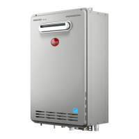
Once the vent terminal location has been
determined, make holes through the exterior wall to
accommodate the vent pipes. Vent pipes must exit
exterior wall horizontally only.
The standard horizontal air intake termination is a
2-inch or 3-inch 90 degree elbow. This prevents rain
or any other liquid for getting into air intake and the
pipe from being pushed back into the structure. The
standard horizontal exhaust outlet termination is a
2-inch or 3-inch pipe which terminates 12 inches
from the air intake termination. Insert a small length
of vent pipe through the wall and connect the
coupling. Connect vent cap or terminal to the vent
pipe on the exterior of the building.
1. Observe minimum clearances. Vent terminals
must be a minimum of 5.5 inches (14 cm) and a
maximum of 24 inches (61 cm) apart horizontally.
2. Cut two 2 1/2” (6.4 cm) diameter holes [for a 2”
(5.1 cm) diameter pipe] or 3 1/2” (8.9 cm) diameter
holes [for a 3” (7.6 cm) diameter pipe] for the
exhaust vent and air intake openings.
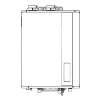
Apply silicone sealant or silicone/latex caulk to seal
the vent pipe to the vent coupling to permit field
disassembly for annual inspection and cleaning.
Completely seal where it passes through the wall
plate and where it is attached to the structure.
Attach the female end of the next vent pipe section
to the male end of the 2-in./3-in. (5.1-cm/7.6-cm)
vent pipe. See “Cementing Joints” on this Use and
Care Manual.
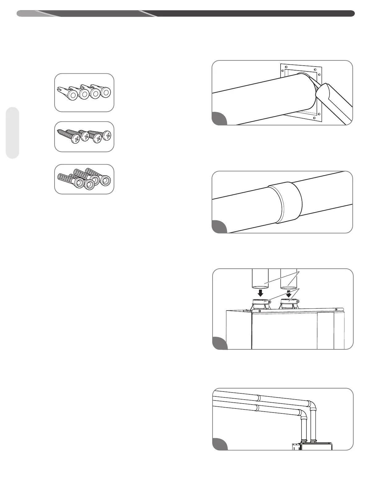
Insert a 2" PVC pipes slowly into an air intake
connector and a flue connector located on top of the
water heater until they stop. DO NOT use cement.
Tighten 2 locking bands to secure 2" PVC pipes.
Complete the rest of the vent pipe installation to the
water heater's flue outlet and air intake.
1
4
2
Venting
3
2” PVC pipes
Locking bands
 Loading...