4 5
2.2 Headgear Assembly Installation (continued)
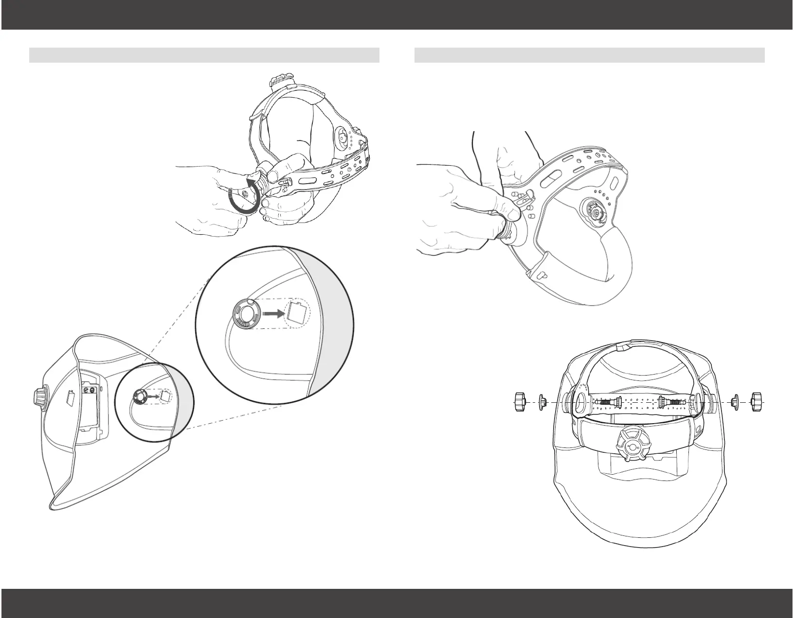
Step 4
Set the “Angle Adjustment
Lever,” #2 to the desired
angle setting. Then, set the
“Headgear Bolt,” #1 into the
desired distance setting.
This illustration shows the
neutral setting. Both sides
of the headgear MUST be on
the same setting for proper
operation of the helmet.
Step 5
Attach the headgear as-
sembly to the helmet by
reinserting the “Head-
gear Bolt,” #1 through
the hole created by
Step 3.
The “Angle Adjustment
Lever,” #2 will t into
the “Interior Headgear
Fitting,” #3.
Complete installation by
screwing the “Headgear
Knob,” #5 onto the end
of the “Headgear Bolt,”
#1.
Step 3 (Not Pictured)
Insert the “Exterior Headgear Fitting,” #4 into the round hole on the
exterior of the helmet that was created in Step 2.
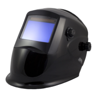
2.2 Headgear Assembly Installation
Insert the “Interior Headgear Fitting,” #3 into the inside of the hel-
met. This round piece has a square outlay with notch that snaps
into a corresponding square hole with notch inside the helmet.
Step 1
Unscrew and remove the
“Headgear Knob,” “Exterior
Headgear Fitting,” and “Interior
Headgear Fitting,” #5, #4, and #3
from one side of the headgear
assembly.
Only #3, the “Interior Headgear
Fitting” is needed in Step 2.
Step 2