Section I :: User
14
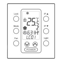
Line up the opening, provided on the bottom you have just unhooked,
with the recessing box and mark the position of the two holes that will
need to be drilled on the wall:
Drill the two holes in the wall and mount the bottom of the panel on it
using three M4x25 screws and their respective plugs, being careful to
lead the cable for the electrical connections out:
Hook the panel back onto the bottom that is now drilled to the wall,
being careful to hook the bottom part on first, and then, by pressing
gently, the top part.
II.2.1.3 Electrical connection
IMPORTANT!
The electrical connection of the unit must be
carried out by qualified personnel, in compliance
with the regulations applicable in the country where
the unit is installed. Non-conforming electrical
connections releases RHOSS S.p.A. from liability
concerning damage to objects and persons.
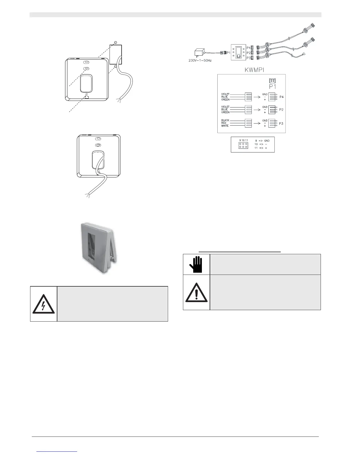
The following are supplied:
x 1 230/12Vdc transformer, the terminal slots onto connector P1
located inside the centralised wired panel
x 2 three-wire cables (blue green purple) that slot onto connectors
P2 – P4 located inside the centralised wired panel
x 1 three-wire cable (black red white) which slots onto connector P3
located inside the centralised wired panel.
The installation technician must set up the connections using small
terminals and a screened cable comprised of 3 twisted wires with an
AWG 14-22 section and the screen. The shield must be connected to
the earth terminal on the unit (on one side only).
On the unit side, pass the cable through the cable through-hole on the
machine. Access the electrical panel, which has a connector installed
inside for this connection.
Note: P2 and P4 are set up electrically parallel.
II.2.1.4 Configurations
Regardless of the centralised wired panel, each unit can be
momentarily managed locally from the remote control or the wired panel
(KWPI): however, remember that the last command sent to the unit
must overwrite the previously saved one.
Simple serial network
It is possible to manage up to 63 units with a single KWPCI.
It is possible to manage the entire network from a PC with the KRSE
supervisor accessory.
Complex serial network
With a maximum of five KWPCI accessories it is possible to manage up
to 315 units (63 units multiplied by 5). It is necessary to manage the
entire network from a PC with the KRSE supervisor accessory.
II.3 INSTRUCTIONS FOR START-UP
IMPORTANT!
The accessory must only be commissioned by
skilled personnel, qualified to work on this type of
product.
DANGER!
Before starting up, make sure that the installation
and electrical connections have been carried out in
compliance with the instructions in this manual.
Also make sure that there are no unauthorised
persons in the vicinity of the machine during the
above operations.
II.3.1 PRELIMINARY CHECKS BEFORE START-UP
Before starting up the unit:
1. the accessory is positioned correctly;
2. the electrical connections are correct;
3. the screws holding the cables are tightened well;
4. the supply voltage is as required;
5. the power absorption of the unit is correct and does not exceed the
maximum permitted.