EasyManua.ls Logo

RIB K1400 Series User Manual

RIB K1400 Series
56 pages
Go to English
To Next Page IconTo Next Page
Page #1 background imageLoading...
Page #1 background image
K800 - K1400
K2200
K FCE K FCM
Operatore
Opérateur
Operator
Torantrieb
Operador
Alimentazione
Alimentation
Power Supply
Stromspannung
Alimentacion
Peso max cancello
Poids maxi portail
Max gate weight
Max Torgewicht
Peso máx verja
Spinta max
Poussée maxi
Max Thrust
Max Schubkraft
Max Empuje
Coppia max
Couple maxi
Max torque
Max. Drehmoment
Coppia max
con radio ricevitore
avec radio recepteur
with radio receiver
mit Empfänger
con radio receptor
Codice
Code
Code
Code
Codigo
K800
FCE -
230V 50/60Hz
800 kg / 1766 lbs
60 kg / 132 lbs 20,4 Nm
no CRX AA30039
FCE - CRX AA30076
FCM - CRX AA31110
FCM ICE CRX AA30054
FCE -
120V 60Hz 51,4 kg / 113 lbs 17,5 Nm
CRX AA30042
FCE - no CRX AA30077
K1400
FCE -
230V 50/60Hz
1400 kg / 3090 lbs
79 kg / 173,8 lbs 27 Nm
no CRX AA30044
FCE - CRX AA30045
FCM - CRX AA31115
FCM ICE CRX AA30056
FCE -
120V 60Hz 88 kg / 193,6 lbs 30 Nm
CRX AA30047
FCE - no CRX AA30048
K2200
FCE -
230V 50/60Hz
2200 kg / 4856 lbs
115 kg / 253 lbs 39 Nm
no CRX AA30049
FCE - CRX AA30078
FCM - CRX AA31120
FCM ICE CRX AA30053
FCE -
120V 60Hz 117,5 kg / 258,5 lbs 40 Nm
CRX AA30052
FCE - no CRX AA30051
ITALIANO pag. 05 / FRANÇAIS pag. 15 / ENGLISH page 25 / DEUTSCH pag. 35 / ESPAÑOL pag. 45
con / avec / with / mit K-CRX

Other manuals for RIB K1400 Series

Question and Answer IconNeed help?

Do you have a question about the RIB K1400 Series and is the answer not in the manual?

RIB K1400 Series Specifications

General IconGeneral
Opening SpeedAdjustable
Closing SpeedAdjustable
Safety FeaturesObstruction Sensing
OverrideManual Hand Release
Ambient Temperature-20°C to +55°C

Summary

Important Safety Instructions

General Safety Guidelines

Essential safety advice for users and installers, covering general precautions for safe operation.

Installation Safety Precautions

Critical safety measures to follow during the gate automation installation process to prevent accidents.

System Overview and Technical Data

System Layout Diagram and Components

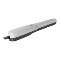
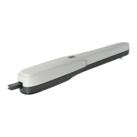
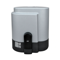
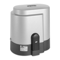
Visual representation of the gate automation system components and their physical layout.

Technical Features and Specifications

Detailed technical specifications for K800, K1400, and K2200 models, including performance data.

Installation and Maintenance Procedures

Pre-Installation Checks and Release Mechanism

Steps to verify gate condition and access manual release before commencing installation.

Motor, Rack, and Limit Switch Fitting

Guidance on installing the motor, rack, and limit switches for proper gate movement.

Routine Maintenance Guidelines

Recommended periodic maintenance tasks for the gate operator system to ensure longevity.

Electrical Connections and Control Settings

Electric Connections Diagram

Wiring diagram for the control board, power supply, motor, and accessories.

Terminal Connections and Command Inputs

Detailed description of terminal points, relays, and command inputs on the control board.

DIP Switch Settings and Operating Modes

Configuration of DIP switches for various operating modes, functions, and safety features.

Motor Rotation Direction Check

Procedure to verify and set the correct motor rotation direction for gate operation.

Programming and Configuration Procedures

Step-by-step guides for programming radio codes, pedestrian opening, and other control settings.

Related product manuals