5
MOTOR AND RACK FITTING
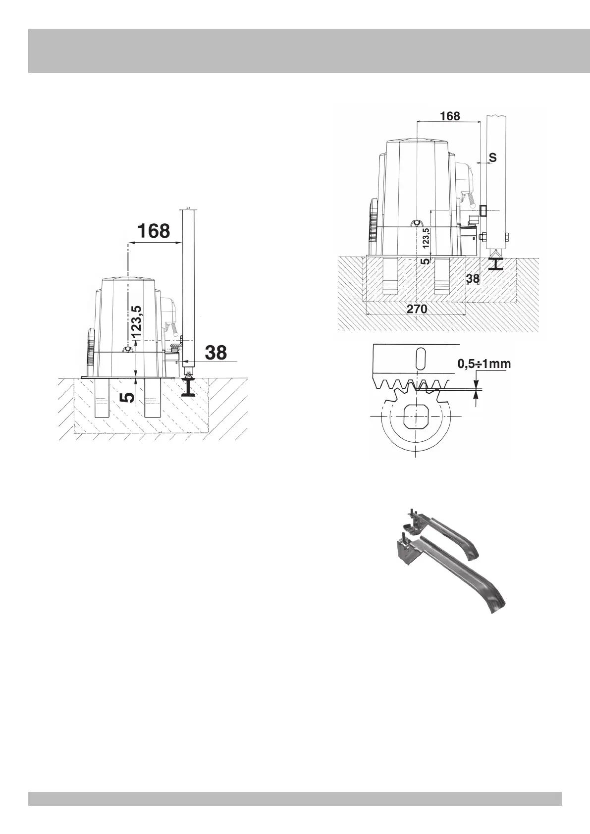
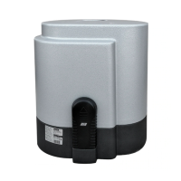
The holes for fixing the nylon rack must be made at 123,5 mm height from the motor
support (at 130mm for the iron rack).
The height of the rack can be adjusted thanks to the slots available on its right -angled
bar.
The height adjusting is necessary to prevent the gate leaning on the driving gear (5 and
6).
To fasten the nylon rack on the gate, drill Ø 5 mm holes on the moving part of the gate
and thread them using a M6 tap thread (Ø 7 mm and M8 for iron rack).
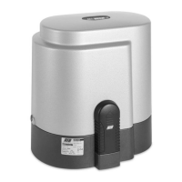
The driving gear needs some 1 mm clearance from the rack.
LIMIT SWITCH FITTING
In order to determine the gate travel length, place two cams at the ends of the
rack (7).
Move the cams on the rack teeth to adjust their opening and closing travel.
To fix the cams to the rack, tighten the screws issued.
N.B: In addition to the electric stop cams mentioned above, you must also install strong
mechanical stops preventing the gate from sliding out from the top guides.
MAINTENANCE
To be carried out exclusively by skilled persons after the power supply to the
motor has been interrupted.
Periodically, when the gate is standstill, clean and keep the guide free from stones and
dirt.
7
5
6
Measurements in mm
Measurements in mm
G
B