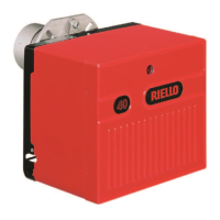
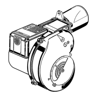
This document describes the Riello 40 GS10D forced draught gas burner, a two-stage operation device designed for installation, use, and maintenance in accordance with the provided instructions.
Function Description
The Riello 40 GS10D is a forced draught gas burner operating in two stages. Its primary function is to provide controlled combustion for heating applications, typically in boilers. The two-stage operation allows for modulated heat output, offering flexibility and efficiency in various heating demands. The burner is designed to operate only in positions 1, 2, 3 and 4 (Fig. 8), with installation in position 1 being preferable.
Important Technical Specifications
Model: RIELLO 40 GS10D, Type 576T1
Heat output (Hi): min - max 29/41 ÷ 106 kW (25,000/35,000 ÷ 91,000 kcal/h)
Fuel: Natural gas, LPG, or Light oil - Natural gas (Family 2 gas)
Gas category: I2H, I2ELL, I2L - I2E, I2 (43,46 ÷ 45,3 MJ/m³ (0°C)), I2E+, I2E(R)B, I2E
Electrical supply: 1/230V/50Hz (or 1/230V/60Hz)
Combustion air temperature: 60 °C max
Fan motor: 2800 - 2940 rpm - rad/s, 230 V, 50 Hz, 90 W, 0.75 A
Ignition transformer: Primary 230 V / 1.8 A - Secondary 8 kV / - 30 mA
Capacitor: 2 µF
Absorbed electrical power: 0.13 kW
Protection level: IP40
Weight: 16 kg
Noise levels: Sound pressure 63.1 dB(A), Sound power 74.7 dB(A)
Maximum dimensions: Flange 185 mm, Height 204 mm, Width 346 mm, Depth 305 mm.
Control box (RMQ88.62C2):
- Mains voltage: AC 230V -15% / +10%
- Mains frequency: 50/60 Hz ±6%
- Built-in fuse: T6.3H 250V
- Energy consumption: 20 VA
- Weight: approx. 280g
- Protection level: IP20
- Safety class: I
- Tightening torque of M4 screw: Max. 0.8 Nm
- Allowed cable length:
- Thermostat: max. 20 m at 100 pF/m
- Air pressure switch: max. 1 m at 100 pF/m
- CP: max. 1 m at 100 pF/m
- Gas pressure switch: max. 1 m at 100 pF/m
- Flame detector: max. 1 m
- Remote reset: max. 20 m at 100 pF/m
- Environmental conditions:
- DIN EN 60721-3-1
- Climatic conditions: Class 3K3
- Mechanical conditions: Class 1M2
- Temperature range: -20 .. +60°C
- Humidity: < 95% RH
Air damper servomotor:
- Voltage and frequency: 230V - 50Hz
- Rotation time: 13 s. 0° - 90°
- Output: 4W
- Ambient temperature: -40 .. +60 °C
- Electric load: 16(4)A, 250V
- Protection level: IP40
The firing rate (Fig. 2) has been obtained considering an ambient temperature of 20°C, an atmospheric pressure of 1013 mbar (approx. 0m above sea level) and with the combustion head adjusted as shown on page 16. The maximum burner output is obtained at 5.25 mbar measured at the pipe coupling (Fig. 3).
Usage Features
Installation: The burner must be installed by qualified personnel in compliance with regulations. It should not be installed outside or in premises with air extractors unless specific precautions are taken. The smoke pipe must be kept open and a natural draft created in the combustion chamber. If the smoke pipe is closed, the burner must be drawn back till the extraction of blast tube from the furnace. Before operating, the air intake must be checked.
Start-up, calibration and operation:
- First start-up: Must be carried out by qualified personnel. Check the adjustment of the head (page 16), damper servomotor (page 16), and gas train (Fig. 21).
- Adjustments: Adjust the head, damper servomotor, and gas train according to the instructions.
- Combustion adjustment: In conformity with EN 676, the application of the burner on the boiler requires observing the minimum and maximum output of the boiler, including verification of CO and CO2 concentrations in the flue gases, their temperatures, and the average temperature of the water in the boiler.
- Air pressure switch: After performing all other burner adjustments, adjust the air pressure switch set to the start of the scale.
- Operation sequence: The burner follows a specific sequence of operations (pre-purge, ignition phase, operation flame OK, operation with weak flame signal, lockout, extraneous light) indicated by LED signals on the control box.
- Normal operation / flame detection: The control box has a function through which it is possible to ascertain the correct functioning of the burner. The number of pulses will measure the probe detection time since the opening of gas valves.
Safety and Prevention:
- General warnings: Always observe safety instructions, including those related to moving parts, explosion hazards, and personal protective equipment.
- Personnel training: Only trained and qualified personnel should install, adjust, and maintain the burner.
- Safety components: The burner incorporates safety components with specified life cycles (e.g., flame control, flame sensor, gas valves, pressure switches, oil regulator, oil pipes/couplings, flexible hoses, fan impeller). These components have defined operational life cycles ranging from 10 to 500,000 operation cycles or 10-15 years.
Maintenance Features
General Maintenance: Periodic maintenance is essential for good operation, safety, yield, and duration of the burner. It reduces consumption and polluting emissions. Maintenance interventions must be carried out by qualified personnel.
Maintenance Frequency: The gas combustion system should be checked at least once a year by a representative of the manufacturer or another specialised technician.
Safety Test - with gas ball valve closed:
- Ensure the correct execution of electrical connections between the gas solenoid valves and the burner to perform safety commissioning.
- Check the following:
- The manual gas ball valve must be closed.
- The electrical contacts of the burner limit switch need to be closed.
- Ensure the contacts of the low gas pressure switch.
- Make a call for burner ignition.
- Start-up cycle must be as follows:
- Starting the fan for pre-ventilation.
- Pre-form the gas valve seal control, if provided.
- Completion of pre-ventilation.
- Arrival of the ignition spark.
- Power supply of the ignition transformer.
- Electrical Supply of solenoid gas valves.
- If the manual gas ball valve is closed, the burner will not light up and its control box will go to a safety lockout condition.
- The actual electrical supply of the solenoid gas valves can be verified by inserting a tester.
Checking and Cleaning:
- The operator must use the required equipment during maintenance.
- Combustion: Check for obstructions in the fuel supply or return lines, in the air suction areas, and in the combustion product waste pipes. Carry out an analysis of the combustion flue gases.
- Combustion head: Check the positioning of the combustion head and fix it properly. Ensure that all components of the combustion head are in good condition.
- Burner: Check for wear or loosen screws. Clean the outside of the burner.
- Fan: Check that the air damper is positioned correctly. Make sure that no dust has accumulated inside the fan or on its blades.
Opening the burner:
- Disconnect the electrical supply from the burner.
- Turn off the fuel interception tap.
- Wait for components to cool down completely.
- Loosen the screws that secure the cover and proceed with maintenance operations.
- Operating safety guards: Repairs to components may only be carried out by respective manufacturers or by personnel instructed by them (fan motor, actuator, air damper servomotor, electromagnetic valves, burner programmer).
Check the operation:
- Start-up of the burner with a sequence of functions (see "Operation sequence of the burner" on page 23).
- Ignition device.
- Air pressure switch.
- Flame monitoring.
- Tightness test of components to the passage of fuel.
Faults - Possible causes - Solutions: The control box generates a sequence of pulses (1 second apart) to identify malfunctions. The document provides a comprehensive table of signals (blinks), corresponding problems, possible causes, and recommended remedies for troubleshooting. For example, 2 blinks indicate "No stable flame signal is detected within the safety time," which could be caused by a faulty gas valve, faulty ionisation probe, or a defective control box. The recommended remedy would be to replace the item or check connections.