EasyManua.ls Logo

Riello 40 User Manual

Riello 40
20 pages
To Next Page IconTo Next Page
Page #1 background imageLoading...
Page #1 background image
2902555 (4) - 11/2011
Installation & Operating Manual
Single stage operation oil burner
CODE MODEL TYPE
3726413 F15 WITH MANUAL AIR SHUTTER 264T
NON-RETROFIT APPLICATIONS
If this burner is being installed in a packaged unit (ie. burner comes with a boiler or furnace), follow
the installation and set-up instructions supplied with the heating unit, as settings may differ from
those shown in this manual.
- The following pages contain information, descriptions and diagrams for the proper installation
and wiring of the burner. Please read carefully before attempting final installation.
- This manual is to remain with the final installation designation. It is the installer’s responsibility to en-
sure that the burner installation and operation instructions mentioned in this manual are followed and
operated within local code authority limits.
WARNING

Other manuals for Riello 40

Question and Answer IconNeed help?

Do you have a question about the Riello 40 and is the answer not in the manual?

Riello 40 Specifications

General IconGeneral
ModelRiello 40
Fuel TypeOil
OperationOne-stage; Two-stage
IgnitionElectronic
ControlOn/Off

Summary

Installation Precautions

Electrical Connections

All electrical connections must comply with CEC Part 1/NEC and local codes. System must be grounded.

Technical Data

Specifications

Provides technical specifications including fuel, firing rate, voltage, motor, capacitor, and pump pressure.

Mounting the Burner to the Boiler or Furnace

Method 1 - Universal Mounting Flange

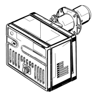
Detailed steps for mounting the burner using a universal mounting flange.

Electrical Connections

Direct Line Voltage

Wiring diagram for direct line voltage (120V AC) control circuit.

Low Voltage

Wiring diagram for low voltage (24V AC) control circuit using primary control 530SE/C.

Nozzle Placement

Electrode Setting

Oil Line Connections

Single Line (Gravity Feed System)

Two Line (Lift System)

Pump Purge

Single Line (Gravity Feed System)

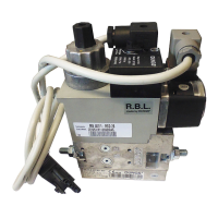
Procedure for purging the pump in a single line system, including warnings.

Two Line (Lift System)

Procedure for purging the pump in a two line system, including warnings.

Setting the Air Adjustment Plate

Burner Set-up Chart

Ducted Combustion Air Intake Applications

Model F15 Burner Setup Chart with 4" Diameter Pipe

Setup chart for 4" diameter pipe, showing firing rates, nozzle sizes, pressures, and air settings.

Burner Start-up Cycle

Burner Start-up Report

Related product manuals