23
COMMISSIONING
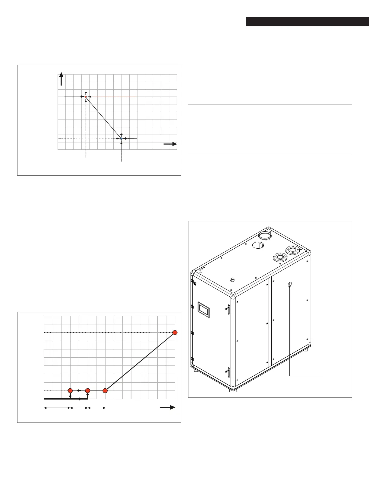
Adjusting the parameters on that screen, the reset curve below
will modify shape and slope to meet the needs of the specic ap-
plication.
20
CH SETPOINT (°C/ )°F
OUTDOOR TEMP. (°C/ )°F
Reset Curve
Design Boiler
93
Reset Curve Outdoor Design
1)Reset Curve Outdoor Mild Weather
2) Warm Weather Shutdown
Reset Cuve
Boiler Mild
Weather
Reset Curve Boiler Maximum
200
82 180
71 160
60 140
12049
10038
27 80
60
16
°C °F
-6
40
4
60
16
80
27
100
38
°F
°C
Reset Curve Boiler Minimum
Fig. 40
Reset Curve
− The boiler will re only when there is a call for heat and the
heating temperature setting is higher than the actual sup-
ply temperature. Hold buttons “+” or “-“ on the Cascade
screen (Fig. 47) to select the desired heating temperature. If
the external temperature sensor is connected (see Section
“2.13.3 Outdoor Temperature Sensor” pag. 16), check that
the calculated temperature is higher than the actual boil-
er temperature and that the outdoor temperature is lower
than “warm weather shut down” temperature.
− The boiler CH setpoint can be controlled by an analog input
signal provided by a remote means such as a Building Man-
agement System or a system controller. The analog input
0-10 VDC, is used to adjust the boiler setpoint between the
CH_Setpoint_Min and the CH_Setpoint_Max settings (Figure
35). To enable this operation mode, the parameter CH mode
must be set to 4 (see Array Control System Manual for ac-
cessing the parameter list).
CH Setpoint
Maximum
CH Setpoint
Minimum
1.51.02.0 10
Voltage
OFFON
ON/OFF
Hysterese
Fig. 41
10VDC Control mode
The CH setpoint Min and CH setpoint Max parameters can be ad-
justed to provide the desired temperature adjustment band. A
heat request will be generated by an input of 1.5 volts or higher.
The setpoint modulation will occur between 2 and 9 volts. The re-
quest for heat will be removed when the voltage drops below 1
volt.
All other safety and control functions associated with the boiler
will react normally to adverse condition and override control of the
analog signal to prevent an upset condition.
3.5.1 Minimum Water Flow (Heat Exchanger
Protection)
This unit is self-protected against low water ow. A ow meter
continuously monitors the water ow to each module. If the water
ow decreases below the minimum stated, the burner automat-
ically shuts off.
3.5.2 Heating System Pressure Test
If the pressure inside the heating circuit falls below the minimum
pressure for the system (7.5 PSI), the appliance switches off and
the 905PB inner display shows “Low water pressure” to indicate
that it is necessary to restore the correct pressure.
Open the lling valve and check the pressure on the temperature/
pressure gauge of Fig. 42.
The error will disappear when the pressure is back at the right
value. To prevent accidental relief valve openings, ll the heating
circuit slowly.
Gauge
Fig. 42
Temperature/Pressure Gauge location