Do you have a question about the Riello Array AR 800 and is the answer not in the manual?
General safety warnings and cautions for installers and operators.
Crucial safety instructions regarding gas, electricity, and flue gas handling.
General warnings about installation, codes, and system compliance.
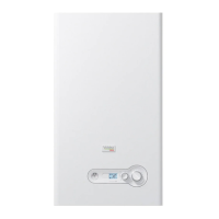
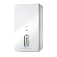
Overview of the Array AR 800 boilers, their purpose and design compliance.
Lists standard components included with the boiler unit.
Specifies intended applications and prohibited uses for the boiler.
Discusses company policy on environmental care and packaging disposal.
Procedure for emergency shutdown by closing the manual gas shutoff valve.
Procedures for startup after prolonged shutdown and safety device testing.
Provides dimensional drawings and connection points of the AR 800 boiler.
Detailed specifications including input/output, pressures, electrical, and physical data.
Diagrams showing the internal components and their numbering.
Detailed list and description of numbered internal components.
Graph illustrating thermal efficiency based on return water temperature.
Outlines conformity to national and local codes, standards, and certifications.
Details system requirements and guidelines for hot water distribution systems.
Introduces the chapter on unpacking, inspecting, and installing the AR 800 boiler.
Instructions for inspecting the unit upon delivery for shipping damage.
Guidance on carefully unpacking the unit and checking for damage.
Requirements for selecting and preparing the installation site, including access and pad.
Specifies minimum clearances required around the boiler for service access.
Instructions for removing packaging and positioning the boiler at its final location.
Guidelines for choosing an appropriate indoor location for the boiler, considering safety and access.
Specifies acceptable water quality parameters to prevent system damage.
Details requirements for connecting the boiler's water supply and return piping.
Explains the function and testing of the low water cutoff (LWCO) sensors.
Describes the high limit safety switch and how to test its functionality.
Information on the factory-installed relief valves and their drain piping.
Instructions for connecting the condensate drain system and priming the siphon.
Further details on condensate management, neutralization, and materials.
Requirements for connecting the gas supply, including shutoff valves and regulators.
Details on natural gas supply pressure and capacity requirements.
Requirement for a manual gas shutoff valve upstream of the boiler.
Guidelines for selecting and installing an external gas pressure regulator.
Procedure for converting the unit from natural gas to propane.
Steps for switching from Natural Gas to LP gas.
Procedure for adjusting combustion air for optimal O2 levels.
Details on adjusting O2 levels for high and low fire settings.
Instructions for connecting the unit to the AC electrical power supply.
Specifies voltage, phase, frequency, and circuit requirements.
Overview of connecting external controls like thermostats and sensors.
How to connect a room thermostat to the control panel terminals.
Configuration and connection of an optional air damper.
Installation and connection of the outdoor temperature sensor.
Requirements and approved materials for venting the boiler.
Further details on venting configurations, clearances, and condensate management.
Illustrates acceptable piping installations for venting and combustion air.
Illustrates different sealed combustion and room air intake configurations.
Lists approved materials for ventilation air and discusses combustion air sources.
Requirements for supplying combustion air, including methods and prohibited environments.
Requirements for supplying combustion air from external openings.
Requirements for supplying combustion air from interior openings.
Emphasizes user instruction, safety precautions, and completion of installation before startup.
Procedure for filling the condensate system as per Section 4.11.
Steps for filling the heating system and checking pressure.
Checks required before initial startup related to gas supply.
How to verify the configured gas type and supply pressure.
Mentions the need for conversion if gas type differs from configuration.
Step-by-step guide to initiate the boiler's operation.
Continues startup procedure, including touchscreen interface and cascade screen.
Covers CH modes, reset curves, and DHW functions.
Explains the unit's self-protection against low water flow.
Procedure for testing the heating system pressure and filling the circuit.
Discusses managing multiple boilers as a coordinated heating system.
Procedure for assigning addresses to boilers in a cascade setup.
Instructions for setting the S1 power switch on cascade controllers.
Guide to operating the Array Boiler using the front control panel.
Overview of the touchscreen control panel and its functions.
Description of the menu structure and available screens.
The initial screen displaying the Riello logo, entry point to the system.
Shows the configuration of cascaded boilers and basic controls.
Displays module status, supply temperature, and access to module details.
Shows module parameters, error status, and access to tests.
Displays real-time performance trends for the last 10 minutes.
Lists recent errors, categorized as blocking or locking errors.
Displays parameters for the service reminder function and history.
Supports installer/service activities with test functions for modules.
Procedure for replacing the front control panel, including configuration checks.
Steps for replacing the main control board and reconfiguring settings.
Notes that no setting actions are required when replacing the touchscreen panel.
Procedure for normal shutdown via the control unit and fuel isolation.
Emergency shutdown steps using main breakers or stop switches.
Information on the company's participation in recycling programs for packaging.
Guidance on recycling old appliance components.
Provides a detailed wiring diagram for the AR 800 unit.
Details wiring connections for the Managing control board.
Details wiring for dependent modules (2/3).
Shows connection diagrams for the 905MN control board and its interfaces.
Diagrams for 905PB display and 905TS touchscreen connections.
Provides a schedule and procedures for regular boiler maintenance.
Tables showing head available for the system with and without glycol.
Information on adjusting capacity for high-altitude installations.
Lists lockout codes, error descriptions, checks, and solutions.
Continues the troubleshooting table with more error codes and solutions.
Further error codes and troubleshooting steps.
Lists warnings and error codes related to communication and sensors.
Details on checking pressure switches and using a multimeter.
Continues troubleshooting steps for pressure switches and air pressure differentials.
Provides example drawings for single unit boiler installation.
Provides example drawings for multiple boiler installation.
Data tables for calculating vent and combustion air system lengths.
Diagrams and specifications for exhaust terminal and air inlet clearances.
Illustrates horizontal and vertical venting termination configurations.
Table showing sensor resistance values at different temperatures.
Lists parameters, ranges, default values, and user levels for boiler settings.
Continues parameter list for DHW and input/output configurations.
Continues parameter list for programmed outputs.
Continues parameter list for cascade settings and protections.
Continues parameter list for cascade settings and PID controls.
Flowchart illustrating the single module operation sequence.
Flowchart detailing the burner ignition sequence.
Flowchart for module cascade (stand-alone boiler) operation.
Flowchart for adding/removing modules in a cascade.
Flowchart for boiler cascade operation logic.
Flowchart for adding/removing boilers in a cascade.
Flowchart for the error checking cycle.