53
SHUTDOWN
53
APPENDIX
APPENDIX
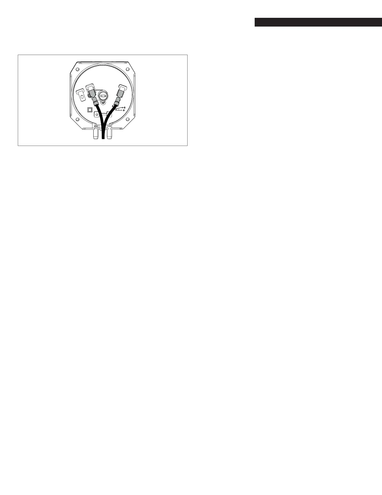
− Disconnect the multimeter and reconnect the wires, as
shown in the picture below.
−
1 (NC)
2 (NO)
3 (COM)
Fig. 69
Wired pressure switch
− Test the pressure switch on the other side of the boiler
(module 4 or 8); repeat the process from Fig. 66 through
Fig. 69.
If the multimeter shows “0” (or any other symbol conrming the
electrical continuity between 1 (NC) and 3 (COM) of the air pressure
switch), the error on the boiler is due to a lack of water on the
hydraulic circuit (or a failure of the pressure switch itself).
If the multimeter shows the air pressure switch circuit between
1 (NC) and 3 (COM) is open, the error is due to an air pressure
differential between boiler cabinet and boiler room higher than
1.4”wc (or a failure of the pressure switch itself).
The root cause is most likely an obstruction/blockage on
combustion air inlet.