24
INSTALLATION
4.14 Field Control Wiring
Each unit is fully wired from the factory with an internal operating
control system. No eld control wiring is required for normal
operation.
However, the control system used with all Array boilers does
allow for some additional control and monitoring features. Wiring
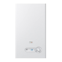
connections for these features are made on the Input / Output (I/O)
terminal strips located behind the removable cover on the inner
side of the front door of the unit, as shown in Fig. 26.
NOTE: Any electrical load connected to the terminal strip (external
pumps, air damper, alarm) must be powered through a relay, not
included in the boiler, to be provided and wired by the installer.
1 2 3 4 5 6 7 8 9 10 11 12 13 14 15 16 17 18 19
LINK
DAMPER
Door
Sensor
Sensor
GND
GND
Sensor
THERMOSTAT
+ + -
101 102 104 105 106 107 108 109 110 111 112103
AIR
DAMPER/
ALARM
MAIN /
CH PUMP
DHW 3-WAY CH
DHW Pump CH Pump
Fig. 26
I/O Terminal Strips
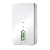
All eld wiring is installed from the rear of the panel by routing the wires
through one of the openings provided on the sides of the cover panel
(see Fig. 27).
Opening for
wires
Fig. 27
Opening on the Cover Panel
4.14.1 Room Thermostat Connection (Enable/Disable)
The Room Thermostat (Enable/Disable) terminals (dry contacts)
come pre-wired closed (jumped) from the factory. For connecting a
room thermostat, the jumper must be removed and the thermostat
wires must be connected to terminals 11 and 12, as shown in Fig. 26.
4.14.2 Air Damper
The Air Damper output comes disabled from the factory. When
connecting an air damper, the Par.126 (Programmable Output 2)
must be set to 10 and the damper wires must be connected to
terminals 101-102-103, as shown in Fig. 26.
The feedback of air damper must be connected to terminals 3-4.
4.14.3 Outdoor Temperature Sensor
If an outdoor temperature sensor is used, the outdoor probe
needs to be connected to terminals 5 and 6 as shown in Fig. 26.
The outdoor probe shall be installed on an outer wall, North or
North/East, away from windows, door, and ventilation grids.
Never install the probe in a position exposed to the sun.
The maximum length is 300’ (100 meters), if the cable length
exceeds 32’ (10 meters) a shielded cable is required and shall be
connected to chassis ground.
NOTE: All sensors and low voltage wiring shall not be routed in
direct contact or near high voltage power.
4.15 Venting
Array boilers must be vented and supplied with combustion and
ventilation air as described in this section.
Installation must comply with local requirements and with the
National Fuel Gas Code ANSI Z223.1. Array boilers vent and intake
air piping can be installed through the roof or through a sidewall.
Any of the vent/air piping methods covered in this manual can be
used. Do not attempt to install the boilers using any other means.
Suitable, UL approved, positive pressure, watertight vent materials
MUST be used for safety and UL certication.
Array AR 800 boiler can use the following material for venting:
Material Standard
Maximum Flue
Temperature (°F)
Approved
Manufacturers
CPVC Schedule
40, 80
ANSI/ASTM
F441
194
Polypropylene ULC S636 230
Centrotherm Eco
Systems (InnoFlue
SW)
AL29-4C
stainless steel
UL 1738
300+, limited only
by rating of seals
For specic venting components (terminals, ttings), contact the
respective vent manufacturer.
9
DANGER: It is extremely important to follow these venting
instructions carefully. Failure to do so can cause severe
personal injury, death or substantial property damage.
7
9
DANGER: Use of cellular core PVC (ASTM F891), cellular core CPVC
or Radel® (polyphenosulfone) in venting systems is prohibited.
9
WARNING: Do not connect this gas appliance with any other
appliance unless approved by manufacturer. Failure to comply
with this WARNING could result in the accumulation of carbon
monoxide gas which can cause severe personal injury or death.