22
INSTALLATION
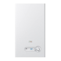
Press “LOW POWER”: the fan will run at the minimum speed.
To adjust the O
2 value at the minimum input, turn the screw “B”
(rotate clockwise to decrease O
2) shown in Fig. 19.
Verify that the value of O
2 is stable and within the range indicated in
the following table (be careful to make small changes and conrm
that the value is stable before making additional adjustment).
Press “Reset” and the boiler return to the “stand by” mode.
Press “Reset” to return the boiler to standby mode.
Repeat above process for all heat exchangers.
Array Combustion Values
Gas Type Max. Fire O
2% Min. Fire O2%
Natural Gas 4.2 – 5.8 4.2 – 5.8
LP Gas 5.0 - 5.6 5.0 - 5.6
Screw “B”
Screw “A”
Fig. 19
O
2
Adjustment
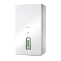
4.13 AC Electrical Power Wiring
External AC power is connected to the unit inside the electrical
box, located on the inside of the front doors. Open the front doors
and remove the panel mounted in the upper part of the left front
door of the unit as shown in Fig. 20 and Fig. 21.
Service
Display
Front Door
Cover Panel
Fig. 20
Front Door Internal Layout AR 800
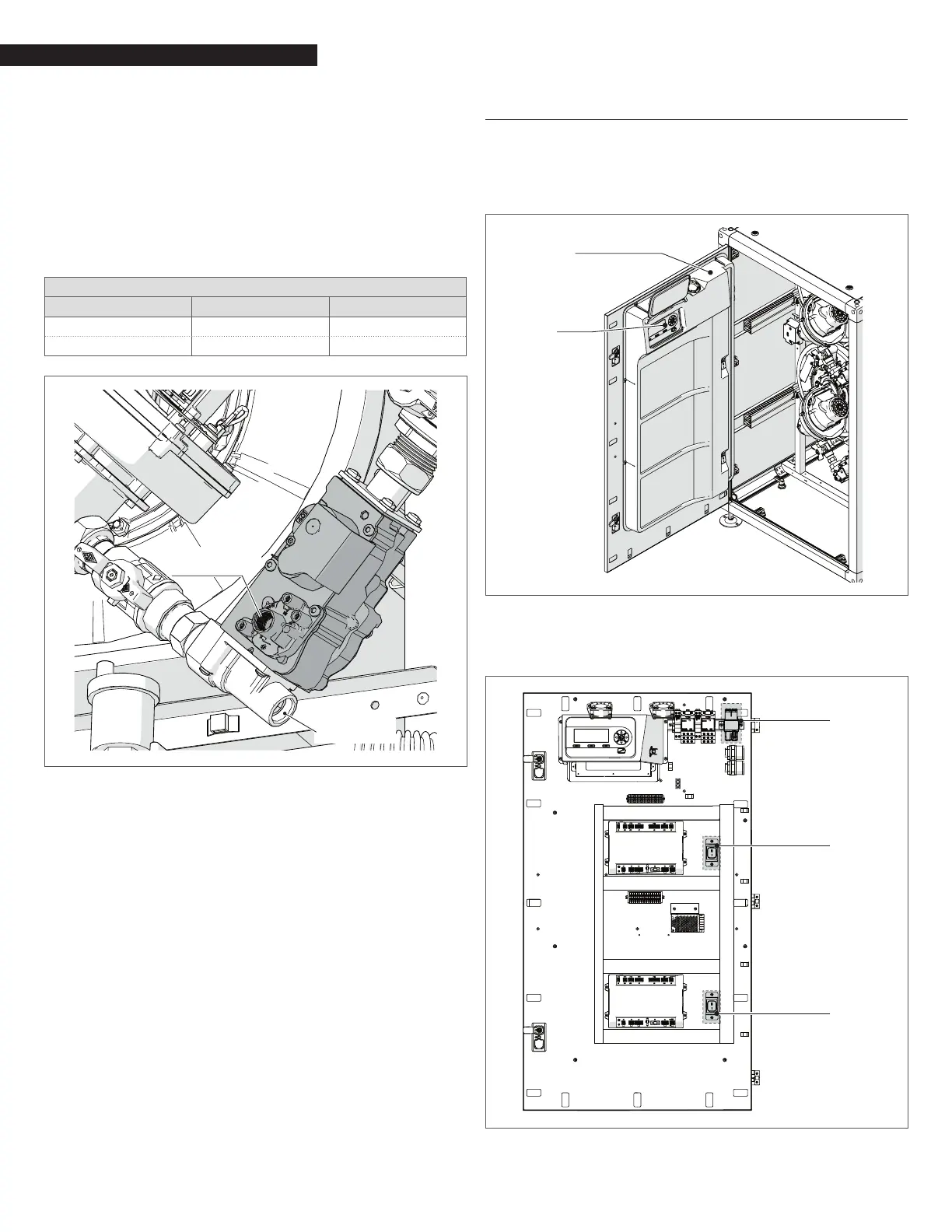
Loosen the screws of the Electrical box cover and remove panel to
access the internal connections shown in Fig. 21.
Front Door
Electrical box
Switch
Switch
Fig. 21
Front Door Electrical box AR 800