21
INSTALLATION
2
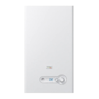
Fig. 15
NG mixer removal
− remove screws (3) in order to get out the mixer
3
3
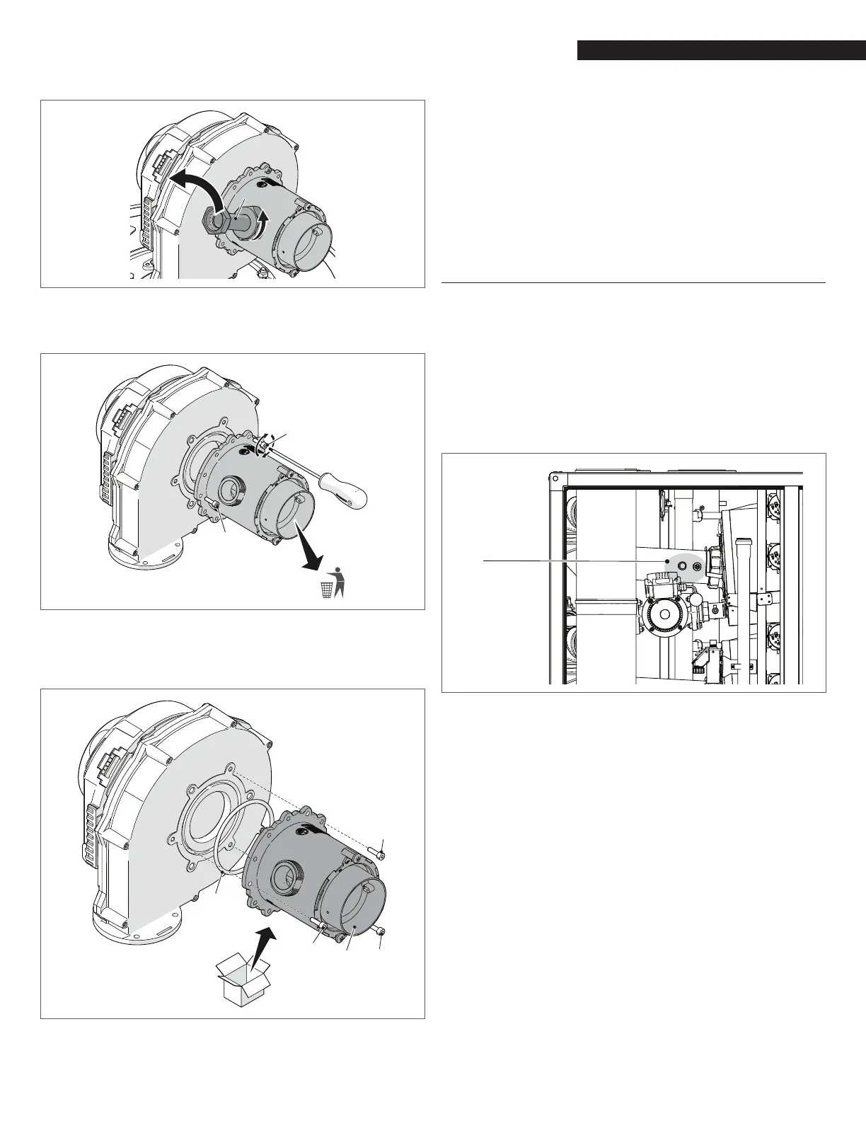
Fig. 16
NG mixer removal
− connect the LPG mixer (4) to the fan, putting in the O-ring
(5) and screws (6)
4
5
6
6
Fig. 17
LPG mixer installation
− reassemble the fan unit and the mixer by reversing the
previous operations.
− Use the PB inner display to enter the appliance conguration
menu and change the parameter #98 from ‘’80‘’ to
‘’81‘’. Follow this path: menu-> setting ->
appliance
->
conguration -> password -> boiler -> managing -> 98
appliance
setting (from ‘’80‘’ to ‘’81‘’) -> conguration
conrmed (‘’yes’’). Repeat the same sequence for each
dependent module.
− Adjust the O2 parameter as explained in next chapter
− Afx the gas type label from the gas conversion kit to the
appliance.
− Repeat above process for all heat exchangers.
4.12.5 Adjusting and Setting O2 Limits
− Insert a combustion analyzer probe into the test port
shown in Fig. 18;
− Go to the Touchscreen and access the Module screen (as
described on “6.3.4 Module Screen” page 35) relevant to
the module under analysis;
− Press “MODULE TEST” button;
− Press “HIGH POWER” button.
Wait 2 or 3 minutes to reach steady state conditions and record
the O
2 value.
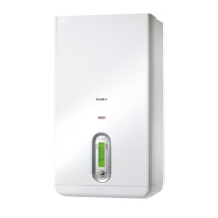
Test port of
the module
Fig. 18
Test Port for Combustion Analysis (available on each
individual heat exchanger)
To adjust the O2 value at high-re turn the screw “A” (rotate
counter-clockwise to decrease O
2) shown in Fig. 19. An allen type
wrench is necessary for this adjustment.
Verify that the value of O
2 is stable and within the range indicated in
the following table (be careful to make small changes and conrm
that the value is stable before making additional adjustment).