23
INSTALLATION
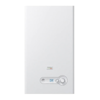
7All of the components in the Electrical box are mounted on a DIN rail.
Main Switch
(backside view)
Terminal Blocks
Fig. 22
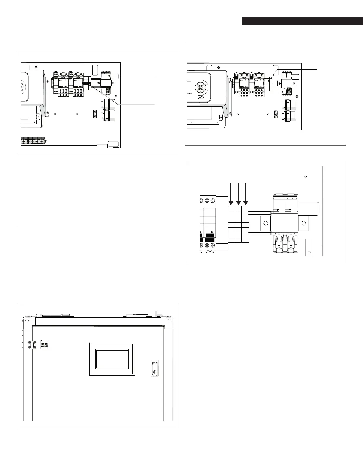
AR 800 Front Door Electrical components
9
WARNING: The main switch shown in Fig. 22 and Fig. 23 does
not remove power from the left door terminal blocks.
NOTE: All electrical conduit and hardware must be installed so that
it does not interfere with the removal of any unit covers, inhibit
service/maintenance, or prevent access between the unit and
walls or another unit.
4.13.1 Electrical Power Requirements
The voltage conguration of Array AR 800 is:
− 120VAC/1PH/60Hz
Each unit must be connected to a dedicated electrical circuit.
NO OTHER DEVICES SHOULD BE ON THE SAME ELECTRICAL CIRCUIT AS
THE BOILER.
The Main Circuit two-pole switch is accessible on the front door to
quickly and safely disconnect electrical service. This breaker does
not remove power on the incoming power supply terminals.
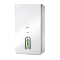
Main Switch
Fig. 23
Main switch
connection
Fig. 24
AR 800 Power supply connection
L N
⏚
Fig. 25
AR 800 120VAC Power supply connection
The installed boiler must be electrically bonded to ground in
accordance with the requirements of the authority having
jurisdiction. In the absence of such requirements, the installation
shall conform to National Electrical Code (NEC), ANSI/NFPA 70 and/
or the Canadian Electrical Code (CEC) Part I, CSA C22.1 Electrical Code.