52
SHUTDOWN
52
APPENDIX
APPENDIX
NOTE
In order to check if the control is functioning properly the following
readings can be taken:
AL Link
24VDC (with S1 Switch On and open circuit). Voltage is variable while
in normal operation depending on data stream.
Pressure Switches
(ie: Gas Pressure, Water Pressure, Flue Pressure, etc) 3.3VDC while
circuit is open.
Safety Switch
(High Limit) 24VDC while open
Flow Meter
5VDC at all times
In addition to the ones listed on the Troubleshooting table, there
are two error messages showing a combination of two potential
failures.
In order to detect which of the combined failures is stopping the
boiler, please go through the following procedures:
1. For Array AR 800: “LWCO/Air inlet block” error message on TS
Boiler screen.
This message shows on touchscreen as a result of two possible
errors:
− Boiler water level below the LWCO probe on the Supply
header.
− Differential between air pressure inside the boiler cabinet
and air pressure of the boiler room higher than 1.4” wc.
In order to discriminate between those two causes, it is suggested
to access the differential air pressure switch inside the boiler
cabinet (left side).
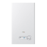
This pressure switch is also normally closed (NC). Conrm it is wired
correctly, with connections on 1 (NC) and 3 (COM), see picture below
1 (NC)
2 (NO)
3 (COM)
Fig. 65
Wired pressure switch
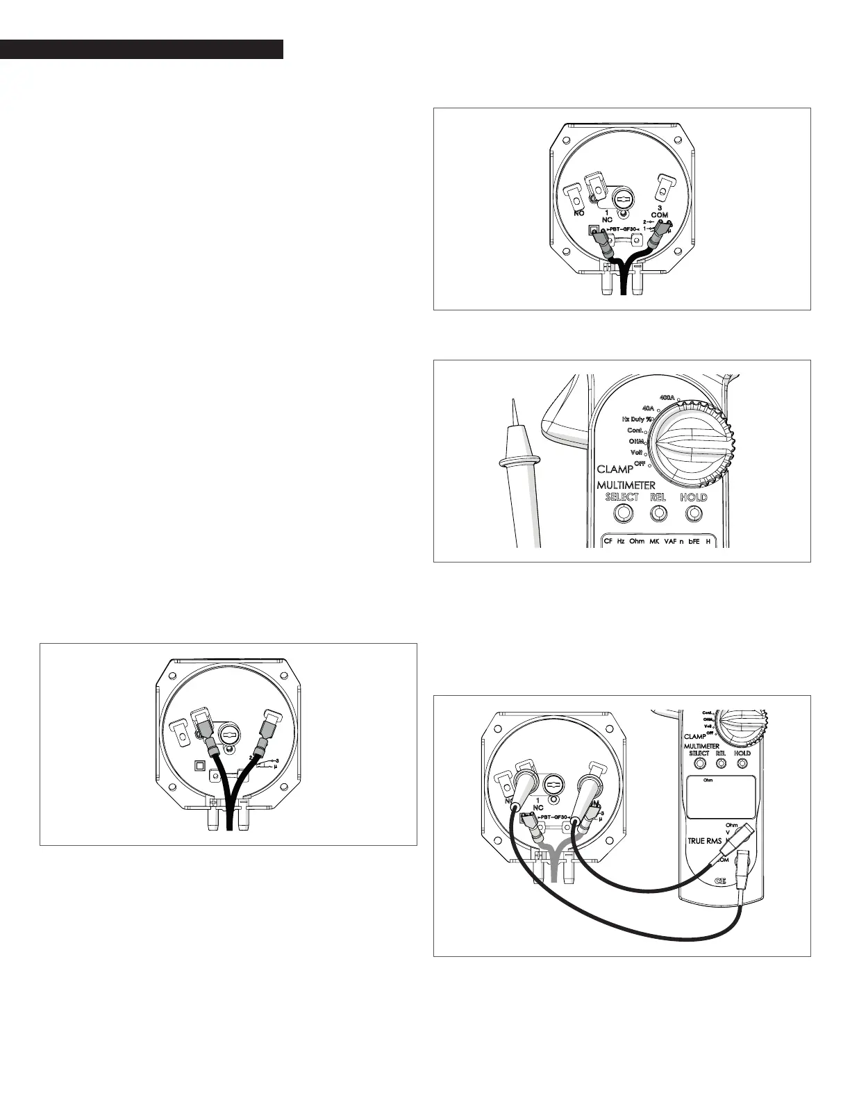
− Disconnect both wires.
Fig. 66
Disconnect wires
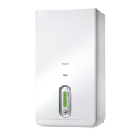
− Set the multimeter device on Ohm (Ω).
Fig. 67
Set multimeter device
− Connect the multimeter probes to 1 and 3 on pressure
switch.
− Check the multimeter display. If the pressure switch
works and is closed (that means the inner pressure of
the condensate trap is lower than 2.2” wc), the display
shows “0” or any other symbol indicating there is electrical
continuity between connections 1 and 3.
1 (NC)
3 (COM)
00.00
Fig. 68
Connect the multimeter probes