EasyManua.ls Logo

Riello CBD 20 PLUS User Manual

Riello CBD 20 PLUS
12 pages
To Next Page IconTo Next Page
Page #1 background imageLoading...
Page #1 background image
HELIOTERM INVERTER
Doc-0074814 Rev. 0
1
IT
Avvertenze preliminari
Montaggio
Montaggio e connessioni pannello di
comando a bordo macchina
Questa istruzione è parte integrante del libretto
dell’apparecchio sul quale viene installato il KIT. A tale
libretto si rimanda per le AVVERTENZE GENERALI e per le
REGOLE FONDAMENTALI DI SICUREZZA.
Infilare il pannello di controllo nella sua sede nella parte
superiore dell’apparecchio e fissarlo con le due viti a corredo
(rif. A).
Per installare la scatola dei collegamenti:
aprire la scatola (rif. B);
incastrare il dente inferiore nell’apposita feritoia (rif. C) sul
fianco dell’apparecchio;
agganciare la parte superiore della scatola al fianco (rif. D);
fissarla con le due viti a corredo (rif. E);
fissare il cavo di terra alla struttura dell’apparecchio
utilizzando la vite a corredo (la forza minima che deve
essere esercitata per l’avvitamento deve essere di circa 2N);
collegare il connettore rapido del motore (FAN_COIL ) a
quello presente sulla scheda (rif. I) *;
nei 2 terminali del morsetto LOCK (rif. L) è presente un ponte
che garantisce il funzionamento delle versioni Design
Inverter e Design Inverter Plus prive di microinterruttore.
Il comando a bordo macchina con selettore di velocità e
ON/ OFF a pulsante, termostato ambiente regolabile da
5 a 40°C, selettore estate inverno e funzione di minima
temperatura invernale (30°C) e massima temperatura
estiva (20°C) è adatto per l’installazione a bordo macchina
e dispone di una uscita a 230 V per il controllo di
un’elettrovalvola.
CBD 20 PLUS - PANNELLO DI COMANDO A
BORDO (BASE)
In alcune parti del libretto sono utilizzati i simboli:
ATTENZIONE= per azioni che richiedono particolare
cautela ed adeguata preparazione.
VIETATO= per azioni che non devono essere
assolutamente eseguite.
Versioni
Codici
20098185
CBD 20 Plus - Pannello di comando a bordo (BASE)
EN
Preliminary instructions
Mounting
Machine onboard control assembly and
connecting
This instruction booklet is an integral part of the manual
of the device on which you install the kit. In that manual,
please refer to the WARNINGS and the BASIC SAFETY RULES.
Place the control panel into its housing in the upper part
of the cooler-convector/cooler-radiator and fix it with the
two supplied screws (ref. A).
To install the connection box:
open the box (ref. B);
insert the lower lug into the special slot (ref. C) on the
side of the appliance;
hook the upper part of the box to the side (ref. D);
fix it with the two supplied screws (ref. E);
fix the earth wire to the cooler-convector/cooler-radiator
structure using the supplied screws (the minimum force
of about 2N must be used when screwing-up);
connect the rapid connector on the motor (FAN_COIL) to
that on the board (ref. I) *;
the 2 terminals of the LOCK clamp (ref. L) feature a jumper
that ensures the operation of the Design Inverter and
Design Inverter Plus versions without microswitch. For
The on-board machine control with speed selector and
ON/OFF button, thermostat adjustable between 5 and
40°C, summer/winter selector and minimum winter
temperature (30°C) and maximum summer temperature
function (20°C) is suitable for installation onboard and has
a 230 V output for solenoid valve control.
CBD 20 PLUS - CONTROL PANEL BOARD
(BASE)
The following symbols are used in this publication:
WARNING = actions requiring special care and
appropriate training.
DO NOT = actions that MUST ON NO ACCOUNT be
carried out.
Versions
Codes
20098185
CBD 20 Plus - Control panel board (BASE)
Question and Answer IconNeed help?

Do you have a question about the Riello CBD 20 PLUS and is the answer not in the manual?

Riello CBD 20 PLUS Specifications

General IconGeneral
TypeControl Panel
SeriesCBD
Input Voltage230 Vac
Frequency50/60 Hz
Relative Humidity95% non-condensing
Output Relay Contact5A 250V AC

Summary

Preliminary Instructions

Symbols Used in Instructions

Highlights symbols like ATTENZIONE and VIETATO for caution and prohibitions.

Product Versions and Codes

Product Codes

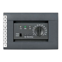
Lists product codes for different control panel versions.

Onboard Control Panel Assembly

Mounting the Control Panel and Connection Box

Step-by-step guide for installing the control panel and its connection box.

Mounting the Air Temperature Probe

Positioning the Air Probe

Instructions on how to route and fix the air temperature probe.

Electrical Connections

Connection Terminals Identification

Identifies key connection terminals like H2, M1, S1, Y1, L-N, RS, FF, HRS, AIR.

Water Probe Management

Water Probe Connection and Operation

Details how the water probe affects startup and operation, including error signals.

Control Panel Description

Control Panel Features and Operation

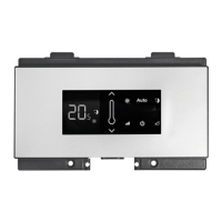
Explains autonomous temperature adjustment, memory function, and environmental dimming.

LED Indicators Overview

LED Status Meanings

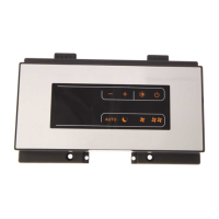
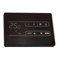
Details the meaning of each LED indicator for fan speed and mode.

Key Functions and Operation

Control Panel Key Descriptions

Explains the function of each key: Temp+, Temp-, Heating/Cooling, mode/off.

General System Power On

Initial System Activation

Instructions for connecting the control panel to mains and initial switch-on.

Performance Function Activation

Activating Performance Mode

Steps to activate the Performance function for increased fan speed.

Device Activation

Selecting Fan Speeds

How to select fan speeds (e.g., Auto, minimum, maximum) using the mode/off key.

Heating/Cooling Mode Setting

Switching Between Heating and Cooling

Procedure to switch between heating and cooling modes using the dedicated key.

Standby Mode Operation

Activating Standby Mode

How to put the device into standby mode by pressing the mode/off key.

Temperature Setting

Adjusting Temperature Settings

Guide to setting desired temperature values using increase/decrease keys.

Fan Speed Adjustment

Cycling Through Fan Speeds

How to cycle through Supersilent, minimum, automatic, and maximum fan speeds.

Key Lock Function

Activating and Deactivating Key Lock

Instructions to activate/deactivate the key lock by pressing temperature keys simultaneously.

Display Brightness Adjustment

Display Dimming and Off Functionality

How to reduce display brightness or turn it off completely.

Device Deactivation (Standby)

Putting Device into Standby

Steps to deactivate the device and enter standby mode using the mode/off key.

Long-Term Shutdown Procedures

Seasonal or Holiday Shutdown

Procedure for seasonal switch-offs or holidays, including deactivating the device.

Error Indications and Troubleshooting

Error Codes and Meanings

Lists error conditions based on LED flashing and their meanings.

Right-Side Hydraulic Connections Motor Connection

Wiring for Right-Side Hydraulic Connections

Instructions for connecting the motor and safety microswitch for right-side hydraulic versions.

Related product manuals