HELIOTERM INVERTER
1
Doc-0091331 Rev. 0
PT
Avisos preliminares
Estas instruções são parte integrante do manual do aparelho
no qual o KIT é instalado. Consulte este manual para as
ADVERTÊNCIAS GERAIS e REGRAS FUNDAMENTAIS DE SEGURANÇA.
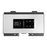
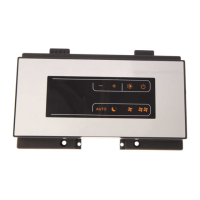
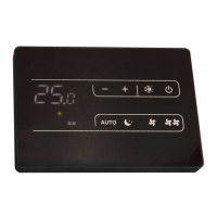
CBD 35 - PAINEL DE COMANDO A BORDO (TOP)
Versões
Códigos
20116408
CBD 35 - Painel de comando a bordo (TOP)
Em algumas partes do manual são utilizados os símbolos:
ATENÇÃO = para ações que exigem cautela especial
e preparação adequada.
PROIBIDO = para ações que não devem
absolutamente ser executadas.
O comando executa a função de temperatura mínima da
água no inverno (30 °C) e temperatura máxima no verão
(20 °C), possui contactos limpos independentes para o
comando de um refrigerador, de uma caldeira e de uma
entrada do contacto de presença.
Possui uma saída de 230 V para o comando da eletroválvula
de verão e inverno.
Insira o painel de controlo na respetiva sede, na parte
superior do aparelho e xe-o com os dois parafusos
fornecidos (ref.A).
Para instalar a caixa das ligações:
abra a caixa (ref.B);
insira o dente inferior na respetiva ranhura (ref.C), na parte
lateral do aparelho;
encaixe a parte superior da caixa na parte lateral (D);
xe-a com os dois parafusos fornecidos (ref.E);
xe o cabo de terra (ref.M) à estrutura do ventiloconvector/
ventiloradiador, utilizando o parafuso fornecido (deve ser
aplicada uma força mínima de aberto de cerca de 2N);
ligue o engate rápido do Motor (MOTOR) ao presente na
placa (ref.I) *;
no par de terminais GRID (ref.L) está presente uma ponte
que assegura o funcionamento das versões Design Inverter
Montagem, conguração e ligações dos
painéis de comando a bordo da máquina
Montagem
EN
Preliminary instructions
This instruction booklet is an integral part of the manual
of the device on which you install the kit. In that manual,
please refer to the WARNINGS and the BASIC SAFETY RULES.
CBD 35 - CONTROL PANEL BOARD (TOP)
Versions
Codes
20116408
CBD 35 - Control panel board (TOP)
The following symbols are used in this publication:
WARNING = actions requiring special care and
appropriate training.
DO NOT = actions that MUST ON NO ACCOUNT be
carried out.
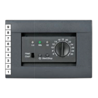
The control panel performs the minimum winter
temperature (30 ° C) and maximum summer temperature
(20 ° C) functions, has independent free contacts to control
a chiller instead a boiler and a presence input.
It has an 230V output for driving the summer and winter
solenoid valves.
Place the control panel into its housing in the upper part
of the cooler-convector/cooler-radiator and x it with the
two supplied screws (ref. A).
To install the connection box:
open the box (ref. B);
insert the lower lug into the special slot (ref. C) on the
side of the appliance;
hook the upper part of the box to the side (ref. D);
x it with the two supplied screws (ref. E);
x the earth wire (rif. M) to the cooler-convector/
cooler-radiator structure using the supplied screws
(the minimum force of about 2N must be used when
screwing-up);
connect the rapid connector on the motor (MOTOR) to
that on the board (ref. I) *;
the 2 terminals of the GRID clamp (ref. L) feature a
Mounting, setting and connection of on-
board machine control panels
Mounting