3
2916224
Signal converter kit
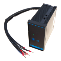
2.4 Terminal board connections
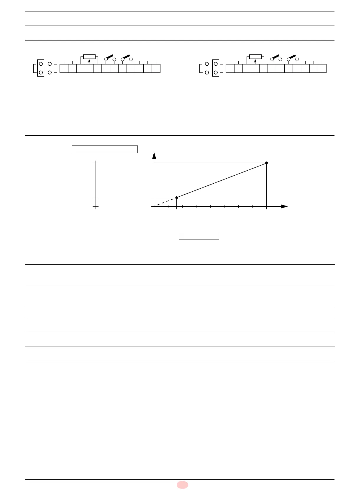
2.5 Input signal
The input signal can be easy adapted to the stroke of the servo-
motor as shown below:
or for other applications:
2.6 E 5202 Converter adjustment
The converter does not require specific calibration; it adapts
the position of the servomotor to the 0/4to20mA (or 0/
2to10V) input signal through combination with the potenti-
ometer's resistance value.
The converter is fitted with a trimmer (Dead Band) posi-
tioned on the front panel; you are anyway recommended to
regulate the trimmer to the maximum value, (TRIM fully
rotated clockwise), to avoid a a reaction that is too frequent
with needless repositioning of the servomotor in the case of
very small variations of the input signal.
The maximum value of the Dead Band is 1%, that corre-
sponds to no repositioning reaction until the input variation
signal is more than 0.2 mA (or 0.1V) (angle of around 1°).
•
Fig. 2
123456789101112
230V
N
IN
+-
INC. DEC.
IN
V
mA
123456789101112
115V
N
IN
+-
INC. DEC.
IN
V
mA
Factory setting
Electrical supply: 230V
Input signal: 0/4 – 20mA
Optional signals (only if necessary)
In the case of 115V electrical supply move the wire
from clamp 10 to clamp 11.
In the case of the 0/2 – 10V input signal move the
jumper onto clamp V.
Fig. 3
2040
Stop
20%
100%
0%
[mA]
1020
[V]
SERVOMOTOR POSITION
INPUT SIGNAL
Minimum power output
Maximum power output
4 – 20mA they correspond to
MIN servomotor position - to the MAX servomotor position
(MIN power output – MAX power output)
See diagram.
2 – 10V they correspond to
MIN servomotor position - to the MAX servomotor position
(MIN power output – MAX power output)
See diagram.
0 – 20mA they correspond to
Servomotor closure position
– MAX servomotor position
See diagram.
0
– 10V they correspond to
Servomotor closure position
– MAX servomotor position
See diagram.