2916224
6
Installation
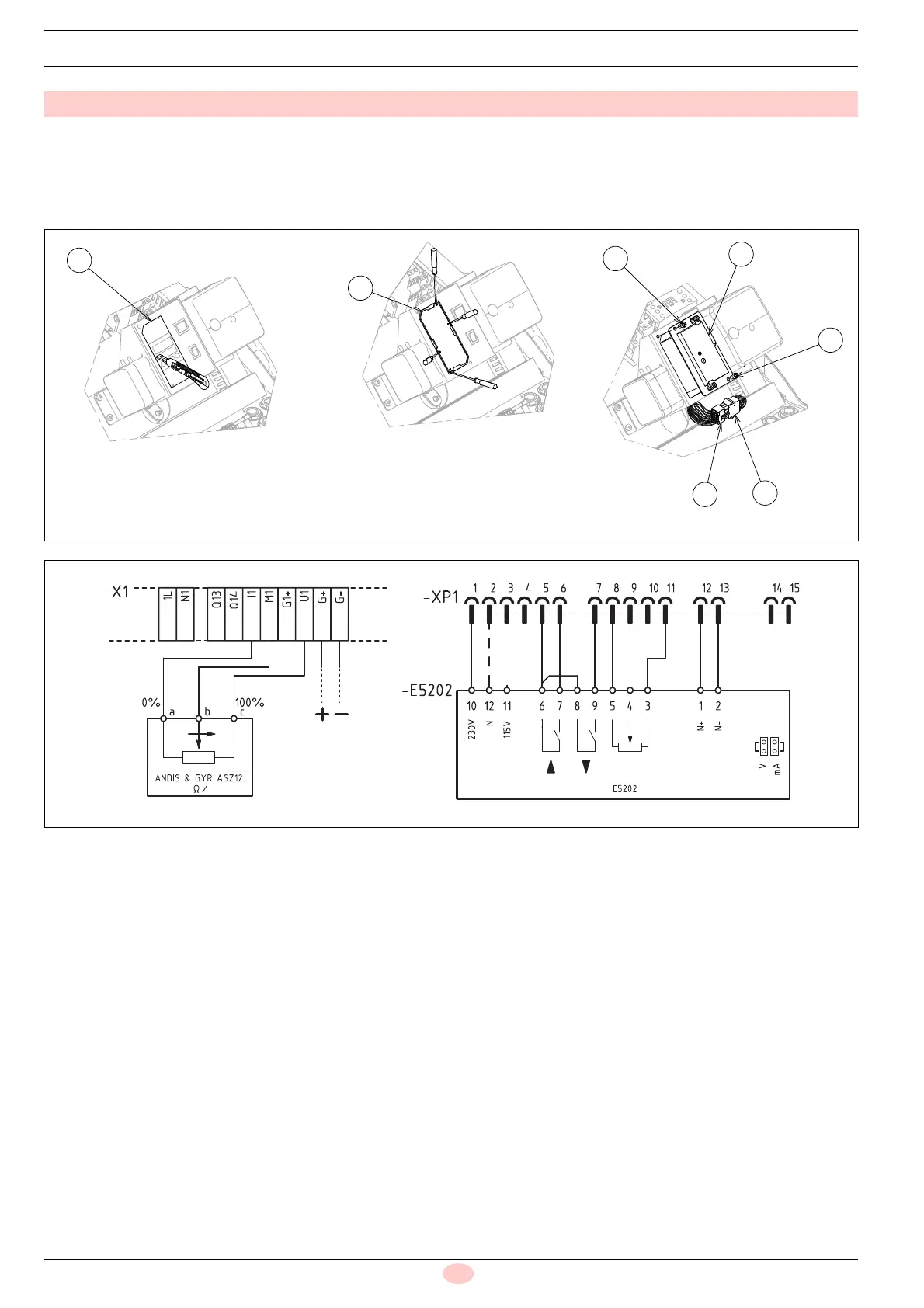
– Cut along the highlighted line in 1)(Fig. 8);
– remove the cover plate 2)(Fig. 8), by prying with a screwdriv-
er in the four indicated points;
– connect the signal converter 3) in the burner bracket and se-
cure with the 2 screws 4).
Electrical connection:
– connect the plug 5) coming from the signal converter to the
corresponding socket 6) of the burner.
See electrical diagram Fig. 9.
Code 20074479
Fig. 8
20093518
20093571
20123712
Fig. 9
Segnale in
ingresso
4-20 mA / 0-10 V
20123509