Do you have a question about the Riello Gulliver RG5S and is the answer not in the manual?
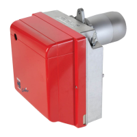
Identifies key physical components of the burner, such as the oil pump, control-box, flange, and nozzle holder assembly.
Details essential operational specifications including output, fuel type, electrical requirements, motor, pump, and power consumption.
Presents dimensional drawings and measurements of the burner, aiding in installation planning and space allocation.
Illustrates the relationship between fuel output, thermal power, and combustion chamber pressure through a graph.
Provides step-by-step instructions for securely mounting the burner flange to the boiler door using provided hardware.
Explains the connection of oil supply pipes, accommodating entry from either side of the burner.
Details pump configuration for two-pipe/one-pipe systems, filter requirements, and priming procedures for reliable fuel delivery.
Outlines the complete electrical connections, including diagrams for the control box, safety devices, and motor.
Guides on setting pump pressure, combustion head, and air damper for optimal performance based on nozzle selection.
Lists suitable nozzle types and provides detailed instructions for their installation and replacement.
Explains the precise adjustment of the combustion head for specific output levels using a regulating rod.
Details the correct positioning of ignition electrodes for reliable spark generation during startup.
Describes the hydraulic system's role in smooth starts and automatic air-flow adjustments, including low flame settings.
Instructions for adjusting the air damper and pump pressure for high-flame operation.
Illustrates normal and lock-out start-up sequences, showing timing for various components and failure conditions.