Do you have a question about the Riello P 300 P/G and is the answer not in the manual?
Statement of compliance with ISO/IEC 17050-1 and technical standards.
Details the manual's importance, purpose, and user requirements.
Outlines danger levels (DANGER, ATTENTION, CAUTION) and associated symbols.
Clarifies the meaning of various safety symbols used throughout the manual.
Guidelines for receiving the system and instruction manual.
Outlines the product guarantee and limitations of manufacturer responsibility.
General safety rules, potential risks, and proper burner usage guidelines.
Specifies training needs for personnel operating and maintaining the burner.
Explains the coding and parameters used to identify burner models.
Lists the different burner models with their specifications and codes.
Provides core technical specifications like output, fuel type, and dimensions.
Details electrical parameters, motor specifications, and ignition systems.
Illustrates burner dimensions with diagrams and measurements.
Lists the components included as standard with the burner package.
Graphs showing burner output ranges based on fuel flow and pressure.
Information on test boilers and combustion chamber dimensions for compliance.
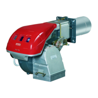
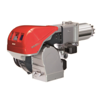
Detailed breakdown and labeling of the burner's various parts.
Identifies and describes components found on the burner's electrical panel.
Technical specifications, usage, and installation notes for the RFGO-A23 control box.
Technical data and important handling notes for the SQM40 servomotor.
Critical safety warnings and requirements before commencing installation.
Guidelines for safe handling and movement of the burner unit.
Steps to verify the burner and its components upon delivery.
Specifies the recommended and prohibited installation orientations.
Instructions for fitting the boiler plate and setting combustion head protrusion.
Guidance on choosing the correct blast tube length for boiler fitment.
Step-by-step process for mounting the burner onto the boiler.
Procedures and precautions for installing the fuel nozzle.
Instructions for correctly positioning the ignition electrodes.
Guidance on selecting and fitting nozzles for emission compliance.
Table listing available nozzles and their flow rates.
Illustrates the relationship between nozzle type, flow rate, and return line pressure.
Safety and installation guidelines for the fuel supply line.
Instructions for correctly connecting the hoses to the fuel pump.
Schematic illustrating the burner's fluid dynamics and components.
Specifications for the pump and step-by-step priming procedure.
Critical safety notes and steps for making electrical connections.
Procedure for calibrating the thermal relay for motor protection.
How to verify and correct the fan motor's direction of rotation.
Essential safety precautions for the initial burner operation.
Steps for adjusting nozzle, combustion head, and pump pressure before ignition.
Method for setting the maximum fuel flow rate using nozzles and variator.
Detailed procedure for adjusting the pressure variator eccentric.
Steps for adjusting the combustion head for optimal modulation.
How to set the air damper via cam and tie-rod adjustments.
Guidance on adjusting servomotor cams for ignition and modulation control.
Procedure for calibrating the oil pressure switch for safety.
Diagrams illustrating standard and lock-out operating sequences.
Steps to verify correct burner operation and settings after adjustments.
Critical safety measures before performing any maintenance tasks.
Steps for checking combustion, head, nozzle, hoses, tank, and pump.
Lists safety components and their recommended replacement life cycles.
Safety warnings and steps for opening and reassembling the burner.
Explains the meaning of each LED indicator on the burner.
Guide on how to use the check mode for diagnostics and commissioning.
Procedures for handling burner lock-out and emergency stop states.
Table correlating LED states with operating statuses and check modes.
Methods for resetting the control device and resolving lock-out conditions.
Explains LED sequences indicating specific fault causes and lock-outs.
Detailed table mapping LED patterns to faults, causes, and remedies.
Detailed explanations of specific faults, their causes, and recommended solutions.
Continuation of detailed fault analysis, causes, and remedies.
Further detailed explanations of faults, causes, and remedies.
Lists various optional accessory kits like soundproofing and modulating operation.
Guide to layout diagrams and reference indications.
Wiring diagram for the star/triangle starting configuration.
Wiring diagram for the RFGO-A23 control system.
Wiring diagram for the RFGO-A23 control system.
Wiring diagram for the RFGO-A23 control system.
Wiring diagram for the RFGO-A23 control system.
Wiring diagram for the RFGO-A23 control system.
Diagrams detailing electrical connections managed by the installer.
Diagrams showing connections for probes, modulation, setpoints, and compensation.
Explains symbols and terms used in the electrical wiring diagrams.
| Fuel Type | Gas |
|---|---|
| Control System | Electronic |
| Flame Supervision | Ionisation probe |
| Noise Level | 65 dB(A) |
| Weight | 45 kg |