Do you have a question about the Riken Keiki GP-591 and is the answer not in the manual?
General introduction and purpose of the manual.
Details the intended applications and usage scenarios of the unit.
Explains the meaning of DANGER, WARNING, CAUTION, and NOTE symbols.
Lists critical danger items and warnings for hazardous areas.
Covers warnings related to detector heads, power sources, grounding, and fuses.
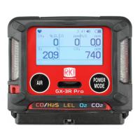
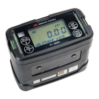
Provides an external view and dimensional drawings of the unit.
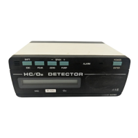
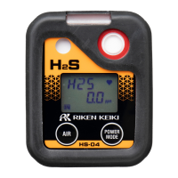
Shows the physical appearance of the indicator/alarm unit.
Emphasizes following cautionary items before operating the unit.
Details the correct procedures for mounting and removing the unit.
Specifies power voltage, tolerance time, and noise considerations.
Suggests fan placement for cooling in control panels.
Discusses measures against lightning surges and grounding.
Lists critical checks to perform before powering on the unit.
Illustrates the operational sequence from standby to detection and maintenance modes.
Details the steps for powering on the unit and initial status indicators.
Explains the functionality of the LED display and indicator lights during operation.
Details how to access and navigate the maintenance mode menu.
Differentiates between gas alarms and trouble alarms.
Explains gas alarm display, power light, and alarm lights.
Defines daily checks for customers and items for regular maintenance.
Explains the process for zero adjustment, noting it's done at the detector head.
Instructions for safely stopping the unit during normal operation.
Guidance on moving the unit and the necessity of recalibration.
Explains the PW/TR light flashing and specific error codes (E-00, E-01).
Advises contacting the agent or Riken Keiki for troubleshooting.
Suggests checking wirings, connections, and power for potential issues.
Covers issues like PW/TR light, abnormal performance, and calibration.
Lists comprehensive technical details including gas detection, output signals, and operating conditions.
| Product Name | GP-591 |
|---|---|
| Manufacturer | Riken Keiki |
| Category | Measuring Instruments |
| Type | Portable Gas Detector |
| Detection Gases | O2, LEL, CO, H2S |
| Measurement Range (LEL) | 0-100% LEL |
| Measurement Range (CO) | 0-1000 ppm |
| Sampling Method | Diffusion |
| Display | LCD |
| Data Logging | Yes |
| Protection Rating | IP67 |
| Detection Principle | Electrochemical, Catalytic combustion |
| Alarm Set Points | Adjustable for each gas |
| Alarm Indicators | Visual, Audible, Vibration |
| Power Supply | Rechargeable battery |
| Operating Temperature | -20°C to 50°C |
| Humidity Range | 0 to 95%RH (non-condensing) |
| Certifications | ATEX, IECEx |