Brivis 5 DGH Manual Controller IM
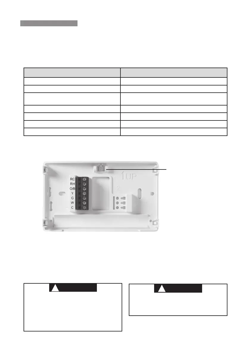
Terminal Designations Terminal Function
RC* Power for Cooling
RH* Power for Heating
O/B
Changeover Terminal-Energized in Heat (B) or Cool (O)
for Heat Pump or Damper Systems
Y** Cooling Relay
G Fan Relay
W** Heating Relay
C
Common wire for 24V (optional with batteries)
*When both RC and RH wires are present, cut RC/RH jumper (see next page).
**For heat pump systems, add a jumper wire to connect terminals Y and W
Leveling Thermostat
Leveling is for appearance only and
will not aect thermostat operation.
WIRING
Refer to equipment manufacturer’s instructions for specic system wiring information. After
wiring, see INSTALLER MENU for proper thermostat conguration. Wiring table shown are
for typical systems and describe the thermostat terminal functions.
Do not use on circuits exceeding specied voltage.
Higher voltage will damage control and could
cause shock or re hazard.
Do not short out terminals on gas valve or primary
control to test. Short or incorrect wiring will burn
out thermostat and could cause personal injury
and/or property damage.
To prevent electrical shock and/or equipment
damage, disconnect electrical power to system,
at main fuse or circuit breaker box,until
installation is complete.
Precautions
• Do not exceed the specication ratings.
• All wiring must conform to local and national electrical codes and ordinances.
• This control is a precision instrument, and should be handled carefully. Rough handing or
distorting components could cause the control to malfunction.
THERMOSTAT INSTALLATION
WIRING
PRECAUTIONS
 Loading...