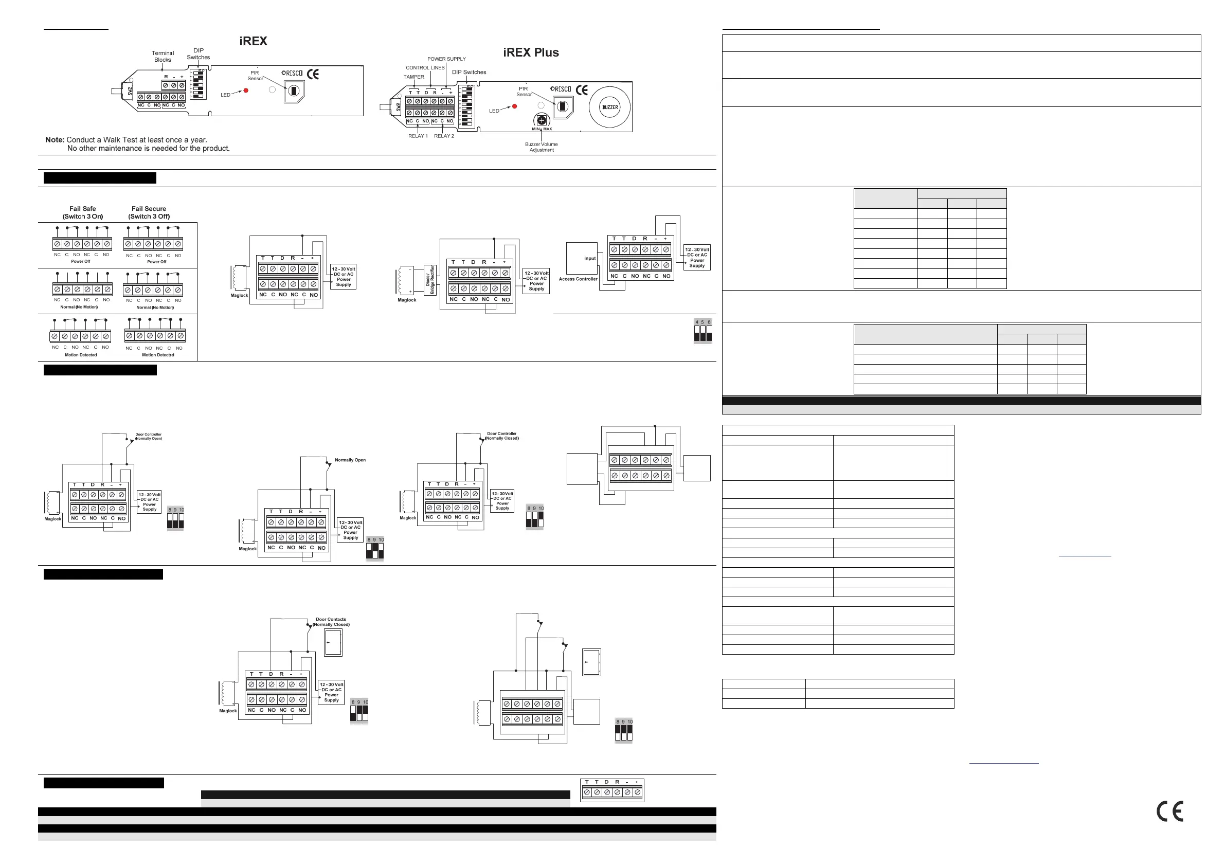
3. WIRING 4. DIP SWITCH OPTIONS
Switch Function Description
1 LED Operation
ON (default) - LED is activated. The LED turns on when motion is detected.
OFF - LED is disabled.
2 Timer Reset
Mode
ON (default) - Relay timer resets when motion is detected during the Relay operation time.
OFF - Relay timer does not reset when motion is detected during the Relay time.
3 Relay Mode This switch defines the relay's operation when power is removed from the iREX.
OFF (default) - Fail Secure mode. When power is removed from the iREX a locked door
will remain locked and secured against opening. (This mode should be authorized by
your local authority)
ON - Fail Safe mode. When power is removed from the iREX a locked door will unlock
and be safely opened.
(See Contact Output Wiring)
4, 5, 6 Relay Timer
Activation
Relay Timer
(seconds)
Switch
4 5 6
1/2 OFF OFF OFF
1 OFF OFF ON
2 OFF ON OFF
4(default) OFF ON ON
8 ON OFF OFF
16 ON OFF ON
32 ON ON OFF
64 ON ON ON
7 Signal
Processing
Determines the detector's PIR detection sensitivity to movement.
ON - High PIR sensitivity
OFF (default) - Low PIR sensitivity.
8, 9, 10
Remote Input
Functions
(See Wiring
options)
Function
Switch
8 9 10
Parallel Door Control (default) OFF OFF OFF
Remote Buzzer Control * OFF OFF ON
Remote iREX Disable * OFF ON OFF
Door Alarm Mode * OFF ON ON
Door Secure Mode * ON ON ON
NOTE:
* Available on iREX Plus only
TECHNICAL SPECIFICATIONS For UL Standard 294 Compliance:
Power
1. RFI is not verified by UL
2. IQ remote feature is UL listed when it is controlled by Access Control units and not burglar
alarm units.
3. NFPA 101 requires the use of Fail Safe relay mode. Fail Secure
relay mode should be used where accepted under Local
Authority jurisdiction.
4. Setting of low sensitivity at the mounting height of 15ft and 8.5ft
may affect the maximum range.
5. Wiring methods shall be in accordance with the National Electrical Code (ANSI/NFPA70),
local codes, and the authorities having jurisdiction.
6. If a fail-secure lock is employed, UL Listed panic hardware must be used to allow exit from
the protected area.
7. All interconnected devices must be UL Listed.
8. Unit must be installed indoors within the protected premises.
9. The unit must be powered by a UL294 Listed Access Control, Power Limited, power supply
capable of 4 hour standby.
EMC Compliance Statement:
Hereby, RISCO Group declares that this equipment is in compliance with the essential
requirements and other relevant provisions of Directive 2014/30/EU. For the CE Declaration of
Conformity please refer to our website: www.riscogroup.com.
RISCO Group Limited Warranty
RISCO Group and its subsidiaries and affiliates ("Seller") warrants its products to be free from
defects in materials and workmanship under normal use for 24 months from the date of production.
Because Seller does not install or connect the product and because the product may be used in
conjunction with products not manufactured by the Seller, Seller can not guarantee the performance
of the security system which uses this product. Sellers obligation and liability under this warranty is
expressly limited to repairing and replacing, at Sellers option, within a reasonable time after the date
of delivery, any product not meeting the specifications. Seller makes no other warranty, expressed
or implied, and makes no warranty of merchantability or of fitness for any particular purpose. In no
case shall seller be liable for any consequential or incidental damages for breach of this or any other
warranty, expressed or implied, or upon any other basis of liability whatsoever. Sellers obligation
under this warranty shall not include any transportation charges or costs of installation or any liability
for direct, indirect, or consequential damages or delay. Seller does not represent that its product
may not be compromised or circumvented; that the product will prevent any persona; injury or
property loss by intruder, robbery, fire or otherwise; or that the product will in all cases provide
adequate warning or protection. Buyer understands that a properly installed and maintained alarm
may only reduce the risk of intruder, robbery or fire without warning, but is not insurance or a
guaranty that such will not occur or that there will be no personal injury or property loss as a result.
Consequently seller shall have no liability for any personal injury, property damage or loss based on
a claim that the product fails to give warning. However, if seller is held liable, whether directly or
indirectly, for any loss or damage arising from under this limited warranty or otherwise, regardless of
cause or origin, sellers maximum liability shall not exceed the purchase price of the product, which
shall be complete and exclusive remedy against seller. No employee or representative of Seller is
authorized to change this warranty in any way or grant any other warranty.
WARNING: This product should be tested at least once a week.
Contacting RISCO Group
RISCO Group is committed to customer service and product support. You can contact us
through our website (www.riscogroup.com) or at the following telephone and fax numbers:
United Kingdom
Tel: +44-161-655-5500
technical@riscogroup.co.uk
US
Tel: +1-631-719-4400
support-usa@riscogroup.com
Ital
Tel: +39-02-66590054
support@riscogroup.it
Belgium
Tel: +32-2522 7622
support-be@riscogroup.com
Spain
Tel:+34-91-490-2133
support-es@riscogroup.com
China
Tel: +86-21-52-39-0066
support-cn@riscogroup.com
France
Tel: +33-164-73-28-50
support-fr@riscogroup.com
Israel
Tel: +972-3963-7777
support@riscogroup.com
All rights reserved. No part of this document may be reproduced in any form without prior
written permission from the publisher.
© RISCO Group 04/18 5IN700PR D
Voltage 12-30 Volts DC or AC
Current Consumption 8mA standby,
iREX: 30mA max (Relay+LED),
iREX Plus: 50mA max at 12/24 VDC
(including Buzzer)
Relay Output Rating 1A @ 30 volts DC or AC, two form
“C” contacts
Tamper Output Rating 50mA @ 30 volts DC or AC
Buzzer Output (iREX Plus) 85dB with adjustable volume
Output Level at 10ft 69dBA
Detection System
Mounting Height 2.3m - 4.6m (7.5ft – 15ft)
Detection range Width From 0.6m (2ft) up to 2.4m (7.9ft)
Physical
Dimensions (LxHxD) 177mm x 50mm x 45mm
Weight 150g
Color Black or White
Environmental
Radio Frequency Interference
(RFI) Immunity
30 V/m from 10 MHz to 2 GHz
Operating Temperature -20°C to 55°C (-4°F to 131°F)
Storage Temperature -20°C to 60°C (-4°F to 140°F)
Humidity Up to 75%
Note: For indoor use only.
ORDERING INFORMATION
Model Description
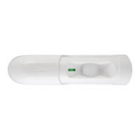
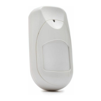
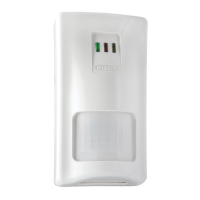
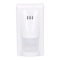
iREX 700 iREX Request-to-Exit PIR White/Black
RK700PRP iREX Plus Request-to-Exit PIR White/Black
This device complies with part 15 of the FCC Rules. Operation is subject
to the following two conditions:
(1) This device may not cause harmful interference, and
(2) This device must accept any interference received, including interference that may
cause undesired operation.
Changes or modifications to this equipment which are not expressly approved by the party
responsible for compliance (RISCO Group's.) could void the user's authority to operate the
equipment.
FCC Note
This equipment has been tested and found to comply with the limits for a Class B digital
device, pursuant to part 15 of the FCC Rules.
These limits are designed to provide reasonable protection against harmful interference
in a residential installation. This equipment generates uses and can radiate radio
frequency energy and, if not installed and used in accordance with the instructions, may
cause harmful interference to radio communications. However, there is no guarantee
that interference will not occur in a particular installation. If this equipment does cause
harmful interference to radio or television reception, which can be determined by turning
the equipment on and off, the user is encouraged to try to correct the interference by
one or more of the following measures:
Reorient or relocate the receiving antenna.
Increase the separation between the equipment and the receiver.
Connect the equipment into an outlet on to a different circuit from that to which the
receiver is connected.
Consult the dealer or an experienced radio/TV technician for help.
Terminal Application
"+" "-" Power Connection
Connect to power supply between (+) and (-) terminal. (Voltage must be between 12-30 VAC or DC)
"NC,C,NO" Contact Output Wiring
Basic Connection: Magnetic Lock Only
During motion detection, power is removed from
the magnetic lock. The relay behaves according
to the Fail Safe/Fail Secure definition.
Spike Protection
Add a diode or bridge rectifier for locks
that are not spike protected.
Wiring to an Access Control System
Note: It is recommended to set the
Relay Timer Activation to 1/2
second.
"R" Input Terminal Wiring
Parallel Door Control (iREX or iREX Plus)
Use to control the door both from the
iREX or from an external device (card
reader, keypad) usually placed on the
other side of the door.
(Dip Switch settings
on iREX Plus)
Remote iREX Disable (IQ feature) *
Use the Intelligent Queuing feature to remotely
enable or disable the iREX from a remote device
(such as a floor switch, additional PIR, Keycard,
Burglar alarm system, etc.). The iREX will only
activate by motion if the "R" terminal is open, or
for 10 seconds after it closes. The iREX is
disabled when the "R" input is closed after a
delay of 10 seconds.
Remote Buzzer Control *
Use this wiring option to control the iREX
buzzer from a remote contact. Buzzer is
activated while R is open. Turning the
buzzer on does not affect the relay.
Wiring the Remote Buzzer Control to
an Access Control System*
Access Controller
12 - 30 Volt
DC or AC
Power
Supply
+
_
NC C NO NC C
NO
TTDR
-
+
Input
Output
"D" Input Terminal Wiring *
Door Alarm Mode *
If the door is forced open or left open for 10
seconds the buzzer turns on.
Door Secure Mode *
When the iREX is activated but the door remains closed, the relay will drop out after
ten seconds. When the iREX is activated and the door is opened and then closed, the
relay will drop out after 2 seconds.
Maglock
+
_
NC C NO NC C
NO
TTD R - +
Door Contacts
(Normally Closed)
Other Inputs
12 - 30 Volt
DC or AC
Power
Supply
+
_
Notes: Relay Timer Mode must be set for at least 16 seconds
The Door Alarm Mode is not to be considered as a UL listed Burglar Alarm System.
"T" Tamper Switch Wiring *
The tamper terminals are connected to the tamper switch, which opens when the cover is opened.
UL NOTE:
To comply with UL Standard 294, connect the tamper terminal to a 24 hour zone in your control panel.
NOTE:
* Available on iREX Plus only
UL NOTE:
Only UL Listed and/or Recognized wire suitable for the application shall be used and the minimum permissible wire size is No. 22 AWG (0.32mm2).
 Loading...