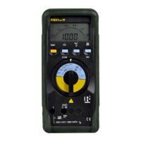
Do you have a question about the Rish Insu20 and is the answer not in the manual?
| Brand | Rish |
|---|---|
| Model | Insu20 |
| Category | Test Equipment |
| Language | English |
Procedures for repair and calibration must be performed by a qualified person after disconnecting the instrument.
Conditions under which the instrument is no longer safe to operate and should be taken out of service.
Instructions for fitting the six 1.5V cells into the instrument before first use or after storage.
Details on connecting an optional mains adapter for long-term measurements without using internal batteries.
How to power on the instrument using the ON/OFF button or by changing the function selector switch.
Describes the auto turn-off feature after inactivity and how to enable 'CONTINUOUSLY ON' mode.
Explains the digital display showing measurement value, decimal point, unit, and function.
The analog indication shows dynamic performance, useful for observing fluctuations and calibration.
User-selectable backlight feature for taking measurements in poor lighting conditions or dark areas.
Steps to prepare for insulation resistance measurement, including selecting test voltage and connecting probes.
Details manual and continuous insulation resistance measurement methods and procedures.
Performing insulation tests for a predetermined duration using the pre-selectable time feature.
Procedures after measurement, including observing residual voltage and automatic discharge of capacitive circuits.
Setting adjustable limits for acoustic signals during resistance and continuity measurements.
How to store up to 10 readings per range using the STORE key and recall them later.
Holding and determining the minimum and maximum measured values over a period.
How to perform continuity tests, including verifying the device is dead and using zero adjustment.
Measuring low resistance values, including using zero adjustment for accuracy.
Procedure to eliminate lead and contact resistance by setting a zero reference value.
Details on using the instrument for AC or DC voltage measurements from 25V to 600V.
Instructions on how to operate the stopwatch function to measure elapsed time up to one hour.
Diagram illustrating the menu command flow for insulation resistance measurements.
How to set the instrument's backlight on or off via the menu structure.
Configuring the limit values for the Go/No-Go function for various measurement ranges.
Setting the timer for continuous insulation resistance measurements.
Accessing previously stored measurement values through the menu.
Describes the logarithmic scale and output voltage graphs for analog indication.
Details the digital display characteristics like segment type, digit count, and over-range indication.
Explains the 'OL' indication for over-range conditions on the digital display.
Specifies the battery type (IEC LR6) and quantity used in the instrument.
Provides estimated service life for battery operation with and without the backlight.
Explains the battery symbol and its conditions that indicate battery replacement is necessary.
Details the input voltage and frequency requirements for the optional mains adapter.
Specifies the output voltage and current of the mains adapter.
Indicates the polarity of the mains adapter output connection.
Indicates the connection point for the mains adapter jack.
Specifies technical data for the cable set, including safety standards and breaking force.
How to test the fuse to determine if it is blown or OK by checking display indications.
Instructions for removing and replacing a defective fuse with a new, specified fuse.
Specifies the instrument's protection class according to IEC standards.
Details the over-voltage category rating (CAT II, CAT III) of the instrument.
Indicates the nominal voltage rating for different categories.
Specifies the contamination degree the instrument is designed to withstand.
States the test voltage applied for safety compliance.
Identifies the EMC standard (Electromagnetic Compatibility) the instrument complies with.
Specifies the nominal temperature range for the instrument.
Defines the operating temperature limits for the instrument.
Specifies the temperature range for storing the instrument.
States the maximum relative humidity allowed for operation.
Indicates the effect of temperature variations on measurements.
Details the mechanical protection rating (IP rating) of the instrument and terminal sockets.
Lists the physical dimensions (Width x Height x Depth) of the instrument.
States the weight of the instrument, including the battery.
Instructions for checking battery condition, replacing batteries, and proper disposal of cells.
Guidance on powering the instrument using an optional mains adapter, including battery cut-off.
How to test the fuse to determine if it is blown or OK by checking display indications.
Instructions for removing and replacing a defective fuse with a new, specified fuse.
Guidance on cleaning and maintaining the instrument's housing to prevent contamination effects.
 Loading...