8.1EMCInstallation Requirements
ThisproducthasbeendesignedtomeetthecertificationoftheEUdirectives
wheninstalledtoagoodcodeofpracticeforEMCinindustrialenvironments,
e.g.
1. Screenedoutputandlowsignalinputleadsorhaveprovisionforfitting
RFsuppressioncomponents,suchasferriteabsorbers,linefiltersetc.,in
theeventthatRFfieldscauseproblems.
Note: Itisgoodpracticetoinstallsensitiveelectronicinstrumentsthatare
performingcriticalfunctions,inEMCenclosuresthatprotectagainstelectrical
interferencewhichcouldcauseadisturbanceinfunction.
2. Avoidroutingleadsalongsidecablesandproductsthatare,orcouldbe,a
sourceofinterference.
3. Toprotecttheproductagainstpermanentdamage,surgetransientsmust
belimitedto2kVpk.ItisgoodEMCpracticetosuppressdifferential
surgesto2kVatthesource.Theunithasbeendesignedtoautomatically
recoverintheeventofahighleveloftransients.Inextreme
circumstancesitmaybenecessarytotemporarilydisconnectthe
auxiliarysupplyforaperiodofgreaterthan5secondstorestorecorrect
operation.
4. ESDprecautionsmustbetakenatalltimeswhenhandlingthisproduct.
TheCurrentinputsoftheseproductsaredesignedforconnectioninto
systemsviaCurrentTransformersonly,whereonesideisgrounded.
Caution
1. Intheinterestofsafetyandfunctionalitythisproductmustbeinstalledby
aqualifiedengineer,abidingbyanylocalregulations.
2. Voltagesdangeroustohumanlifearepresentatsomeoftheterminal
connectionsofthisunit.Ensurethatallsuppliesarede-energisedbefore
attemptinganyconnectionordisconnection.
3. Theseproductsdonothaveinternalfusesthereforeexternalfusesmust
beusedtoensuresafetyunderfaultconditions.
8.Installation
Mountingisbyfoursideclamps,slidethesideclampsthroughsideslottillsideclamp
getsfirmlylockedinagroove(Referfig.)Considerationshouldbegiventothespace
requiredbehindtheinstrumenttoallowforbendsintheconnectioncables.
AsthefrontoftheenclosureconformstoIP54itisprotectedfromwaterspray
fromalldirections,additionalprotectiontothepanelmaybeobtainedbythe
useofanoptionalpanelgasket.Theterminalsattherearoftheproduct
shouldbeprotectedfromliquids.
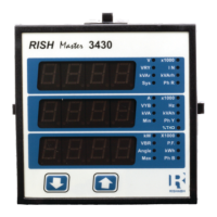
TheshouldbemountedinareasonablystableambientRish3430Master
temperatureandwheretheoperatingtemperatureiswithintherange
0
-10to55C.Vibrationshouldbekepttoaminimumandtheproductshould
notbemountedwhereitwillbesubjectedtoexcessivedirectsunlight.
SLIDEINTHISDIRECTIONANDLOCK
PANEL
RISHMASTER3430
9.Connection Diagrams
3-PHASE4-WIREUNBALANCEDLOAD
DIGITALMETERINGSYSTEM
2 5 8 11 1 3 4 6 7 9
13 14
LN
AUX
SUPPLY
P1
S1
S1
P1
P1
S1
L1
L2
L3
N
L
O
A
D
3-PHASE3-WIREUNBALANCEDLOAD
DIGITALMETERINGSYSTEM
P1
S1
P1
S1
LN
AUX
SUPPLY
L1
L2
L3
N
L
O
A
D
2 5 8 3 4 6 7 9
6.Pulseoutputoption
Thepulseoutputgivespulsesattherateproportionaltothemeasuredenergy.
Therearetwooptionsavailable,
1)OnePulseOutput:Relay1canbeconfiguredeithertoActive(Import/Export)energy
orRea.
2
Thepulsedivisorandpulsewidth(duration)canbeconfigured.Whentwopulseoutputs
arefitted,theyshareacommondivisorvalueandpulsewidth
ctive(Import/Export)energyorApparentenergy
)TwoPulseOutput:HereitispossibletoassignRelay1andRelay2to
Active(Import/Export)energy
orReactive(Import/Export)energyorApparentenergy.
.
NOTE:
IfsystempowerisselectedinWthendefaultpulserateis1pulseperWh(upto3600W).
IfthesystempowerisscaledinkWthendefaultpulserateis1pulseperkWh
(upto3600kWh).Ifthesystempowerisover3600kWhthenpulserateis1pulseperMWh.
8.2CaseDimensionandPanelCutOut
3.78”
96mm
FRONTDISPLAY
AREA
3.78”
96mm
3.15”
80mm
3.62”
92mm
PANELCUTOUT
3.62”
92mm
MAXPANELTHICKNESS0.18”,5mm
8.4AuxiliarySupply
Rish3430Master shouldideallybepoweredfromadedicatedsupply,however
itmaybepoweredfromthesignalsource,providedthesourceremainswithin
thelimitsofthechosenauxiliaryvoltage.
8.5Fusing
Itisrecommendedthatallvoltagelinesarefittedwith1ampHRCfuses.
8.6Earth/GroundConnections
Forsafetyreasons,CTsecondaryconnectionsshouldbegroundedin
accordancewithlocalregulations.
8.3Wiring
Inputconnectionsaremadedirectlytoscrew-typeterminalswithindirect
wirepressure.Numberingisclearlymarkedintheplasticmoulding.Choiceof
cableshouldmeetlocalregulations.TerminalforbothCurrentandVoltage
inputswillacceptupto3mmx2diametercables.
2
Note:Itisrecommendedtousewirewithlugfor
connectionwithmeter.
OperatingMeasuringRanges
Voltage
5..120%ofRatedValue
Current 5..120%ofRatedValue
Frequency 40..70Hz
System CT primary values
Std.Valuesupto4kA(1or5Ampsecondaries)
10.Specification:
System
3Phase3Wire/4Wireprogrammableatsite
Inputs
Nominal input voltage
(Three wire and Four wire)
Max continuous input
voltage
Max short duration input
voltage
Nominal input voltage burden
57.7V to277V (100V to480V )
L-N L-N L-L L-L
120%ofRatedValue
2 x RatedValue
(1s application repeated 10 times
at10sintervals)
0.2VA approx. perphase
Nominal input current 1A/5AACrmsprogrammableatsite
Max continuous input current 120% of RatedValue
Nominal input current burden 0.6VA approx. per phase
Maxshortdurationcurrentinput
20x(1sapplicationrepeatedRatedValue
5timesat5min.intervals)
Auxiliary
Standard nominal a.c. supply
110V,230V,380VAC,
voltages
a.c. supply voltage tolerance +20%/-15%ofRatedValue
a.c. supply frequency range 45 to 66 Hz
a.c. supply burden 4.5V
A
100-250VACorDC
PowerFactor
0.5Lag...1...0.8Lead
ReferenceconditionsforAccuracy:
0
23C+2C
50or60Hz2%+
Sinusoidal(distortionfactor0.005)
RatedValue1%+
Referencetemperature
Inputfrequency
Inputwaveform
Auxiliarysupplyvoltage
Auxiliarysupplyfrequency
Nominalrangeofuseofinfluencequantitiesformeasurands
50..120%ofRatedValue
10..120%of RatedValue
RatedValue 10%+
0
0to50C
Voltage
Current
Inputfrequency
Temperature
Auxiliarysupplyvoltage
Auxiliarysupplyfrequency
Display
3line4digits.Digitheight11mm
Approx.1seconds
LED
Update
Controls
Twopushbuttons
UserInterface
Standards
IEC61326
10V/mmin-Level3industriallowlevel
electromagneticradiationenvironment
IEC61000-4-3.
IEC61010-1,Year2001
EMCImmunity
Safety
Isolation
2.2kVRMS50Hzfor1minute
betweenallelectricalcircuits
Dielectricvoltagewithstand
testbetweencircuitsand
accessiblesurfaces
TemperatureCoefficient
0
0.025%/CforVoltage(50..120%ofRatedValue)
0
(ForRatedvaluerangeofuse
Errorchangeduetovariationofan
influencequantity
2*Errorallowedforthereference
conditionappliedinthetest.
RatedValue1%+
RatedValue 10%+
RatedValue 10%+
0
0.05%/CforCurrent(10..120%ofRatedValue)
0
0...50C)
Referthediagramforexplanation
7.PhaserDiagram:
Inductive
Capacitive
Capacitive
Inductive
Connections Quadrant
Power(P)
Signof
Active
Power(Q)
Signof
Reactive
Factor(PF)
Signof
Power
Inductive/
Capacitive
Import
1
+P
+Q
+
L
Import
4
+P
-Q
+
C
Export
2
-P
+Q
-
C
Export
3
-P
-Q
-
L
InductivemeansCurrentlagsVoltage
CapacitivemeansCurrentleadsVoltage
WhenRISHMaster3430displaysActivepower(P)with“+”(positivesign),
theconnectionis“”.Import
WhenRISHMaster3430displaysActivepower(P)with“-”(negativesign),
theconnectionis“”.Export
Accuracy
Voltage
Current
+0.5%ofrange(50...100%ofRatedValue)
+0.5%ofrange (10...100%ofRatedValue)
Frequency 0.15%ofmidfrequency
ActiveEnergy
+1%asperIEC62053-21
ActiveP.F.(0.866lag...1...0.866lead)
+0.5%ofrange(10...100%ofRatedValue)
ActivePower
+0.5%ofrange(10...100%ofRatedValue)
Re-ActivePower
+0.5%ofrange(10...100%ofRatedValue)
ApparentPower
Re-ActiveEnergy
+1%asperIEC62053-21
(0.866lag...1...0.866lead)
ApparantEnergy
+1%asperIEC62053-21
PowerFactor
+1%ofrange
Angle
+1%ofrange
AnalogOutput
+1%ofOutputendvalue
IEC60529
IPforwater&dust
 Loading...