Do you have a question about the Rish Master 3430 and is the answer not in the manual?
Enables or disables unauthorized access to set-up screens using a four-digit number.
Configures the system type, supporting 3-phase 3-wire or 4-wire configurations.
Sets the nominal full scale voltage for the PT, displayed in kilovolts.
Sets the nominal full scale secondary voltage from the PT, defining the transformer ratio.
Sets the nominal full scale current for the CT, displayed in Amps.
Sets the secondary value for the CT (5A or 1A).
Allows resetting all parameters, energy counts, minimum, or maximum values.
Configures the unique address for the instrument on the RS 485 network.
Sets the communication speed (baud rate) for the RS 485 port.
Configures parity and stop bits for RS 485 serial communication.
Assigns a measured parameter to the analog output 1.
Assigns a measured parameter to the analog output 2.
Explains mapping parameters to user-assignable registers for data access.
Specifies protocol, baud rate, parity, and stop bits for RS 485 communication.
| Category | Measuring Instruments |
|---|---|
| Type | Digital Multimeter |
| Diode Test | Yes |
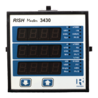
| Model | Master 3430 |
| AC Current Range | 660µA / 6600µA / 66mA / 660mA / 6.6A / 10A |
| Continuity Test | Yes |
| Safety Category | CAT III 600V |
| Measurement Parameters | Voltage, Current, Resistance, Capacitance, Frequency, Temperature |
| Temperature Range | -40°C to 1000°C |
| Safety Standards | IEC 61010-1 |