VRY
KVAr
Sys
V
A
VYB
KVA
Min
KW
VBR
Angle
Max
x1000
KVArh
x1000
x1000
IN
PhR
Hz
KVAh
PhY
P.F.
KWh
PhB
VRY
KVAr
Sys
V
A
VYB
KVA
Min
KW
VBR
Angle
Max
x1000
KVArh
x1000
x1000
IN
PhR
Hz
KVAh
PhY
P.F.
KWh
PhB
Volts1
ParameterNo.
Parameter
0
1
2
Volts2
2
3
Volts3
None
4
IL1
5
IL2
6
IL3
7
W1
8
W2
9
W3
10
VA1
11
VA2
12
VA3
13
VAr1
14
VAr2
15
VAr3
16
*PF1
17
*PF2
18
*PF3
19
*PA1
20
*PA2
21
*PA3
22
VoltsAve.
24
CurrentAve.
27
Wattssum
29
VAsum
31
VArsum
32
*PFAve.
34
*PAAve.
36
Freq.
101
VRY
102
VYB
103
VBR
113
INeutral
3P4W 3P3W
X
X
X
X
X
X
X
X
X
X
X
X
X
X
X
X
X
X
X
ParameterforAnalogoutput:
5.RS485(ModBus)Output:
RISHMASTER3430supportsMODBUS(RS485)RTUprotocol(2-wire).
Connectionshouldbemadeusingtwistedpairshieldedcable.All"A"and"B"connectionsaredaisychained
together.Thescreensshouldalsobeconnectedtothe“Gnd”terminal.Toavoidthepossibilityofloopcurrents,
anEarthconnectionshouldbemadeatonepointonthenetwork.Loop(ring)topologydoesnotrequireany
terminationload.Linetopologymayormaynotrequireterminatingloadsdependingonthetypeandlength
ofcableused.Theimpedanceoftheterminationloadshouldmatchtheimpedanceofthecableandbeatboth
endsoftheline.Thecableshouldbeterminatedateachendwitha120ohm(1/4Wattmin.)resistor.
RS485networksupportsmaximumlengthof1.2km.IncludingtheMaster,amaximumof32instruments
canbeconnectedinRS485network.ThepermissibleaddressrangeforRISHMASTER3430isbetween
1and247for32instruments.BroadcastMode(address0)isnotallowed.
ThemaximumlatencytimeofanRISHMASTER3430is200msi.e.thisistheamountoftimethatcanpass
beforethefirstresponsecharacterisoutput.
Aftersendinganyquerythroughsoftware(oftheMaster),itmustallow200msoftimetoelapsebefore
assumingthattheRISHMASTER3430isnotgoingtorespond.Ifslavedoesnotrespondwithin200ms,
Mastercanignorethepreviousqueryandcanissuefreshquerytotheslave.
Accessing4XregisterforReading&ChangingthesettinginsideRISHMaster:
Eachsettingisheldinthe4Xregisters.ModBuscode03isusedtoreadthecurrentsettingandcode16
isusedtowrite/changethesetting.
ExceptionCases:
AnexceptioncodewillbegeneratedwhenRishMaster3430receivesModBusquerywith
validparity&errorcheckbutwhichcontainssomeothererror(e.g.Attempttosetfloatingpointvariableto
aninvalidvalue)Theresponsegeneratedwillbe“Functioncode”ORedwithHEX(80H).
Theexceptioncodesarelistedbelow
01
Illegalfunction
Thefunctioncodeisnotsupportedby3430
02
IllegalData
Address
Attempttoaccessaninvalidaddressoranattempttoread
orwritepartofafloatingpointvalue
03
IllegalData
Value
Attempttosetafloatingpointvariabletoaninvalidvalue
Functioncode:
03
ReadHoldingRegisters
Readcontentofread/writelocation(4X)
04
ReadinputRegisters
Readcontentofreadonlylocation(3X)
16
PresetsMultipleRegisters Setthecontentofread/writelocations(4X)
4.AnalogOutput(optional):
Thismoduleprovidestwod.c.isolatedoutputs.Therearetwooutputoptions
1)Two0-1mAoutputs,internallypowered.
2) Two4-20mAoutputs,externallypowered.
The0-1mAoutputmodulehasan0Vreturnoneachendofthe4wayconnector
(Pleaserefersection10forconnectiondetails)
The4-20mAoutputmodulemustbepoweredfromanexternal24Vd.c.Source.
(Pleaserefersection10forconnectiondetails)
OnbothmodulestheoutputsignalsarepresentonpinsA1&A2.
TheseoutputscanbeindividuallyassignedtorepresentanyoneofthemeasuredanddisplayedParameters.
Allsettlingsareuserconfigurableviatheuserinterfacescreen.SeeAnalogo/pselection
(section3.2.15&3.2.16)fordetails.
VRY
KVAr
Sys
V
A
VYB
KVA
Min
KW
VBR
Angle
Max
x1000
KVArh
x1000
x1000
IN
PhR
Hz
KVAh
PhY
P.F.
KWh
PhB
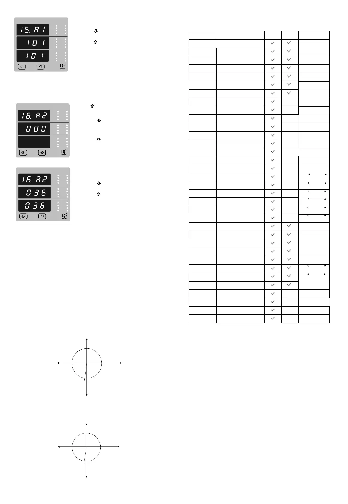
Pressingthe“Down”keywillre-enterthe“Analogoutput1Edit”
Analogoutput1Confirmation:
Pressingthe“Up”keysetsthedisplayedvalueandwilladvance
totheAnalogoutput2selection(seesection3.2.16)
VRY
KVAr
Sys
V
A
VYB
KVA
Min
KW
VBR
Angle
Max
x1000
KVArh
x1000
x1000
IN
PhR
Hz
KVAh
PhY
P.F.
KWh
PhB
VRY
KVAr
Sys
V
A
VYB
KVA
Min
KW
VBR
Angle
Max
x1000
KVArh
x1000
x1000
IN
PhR
Hz
KVAh
PhY
P.F.
KWh
PhB
3.2.16AnalogOutput2Selection:(Optional)
Thisscreenisforanalogoutput2only.Itallowstheusertosetanalogoutput2tocorrespondingmeasured
parameter.Refertable“ParameterforAnalogoutput“.
Pressing“Up”keyacceptsthepresentvalueand
returntomeasurementscreen.
Pressingthe“Down”keywillenterthe“Analogoutput2Edit”
modeandscrollthevalues,asperTable
“ParameterforAnalogoutput”
Pressingthe“Up”keyadvancetotheAnalogoutput2
confirmationscreen.
Pressingthe“Down”keywillre-enterthe“Analogoutput2Edit”
Analogoutput2Confirmation:
Pressingthe“Up”keysetsthedisplayedvalueandwillreturn
tomeasurementscreen.
Range
0-100%
0-100%
0-100%
0-100%
0-100%
0-100%
0-100%
0-120%
180/0/-180
0-100%
0-100%
45to66Hz
0-100%
0-100%
0-100%
0-100%
Note:Parameters1,2,3areL-NVoltagefor3P4W&L-Lfor3P3W.Voltage
*Note:Referdiagrams
0
0
( 12 mA)
270
0
( 8 mA) 90
0
( 16 mA)
181
0
( 4 mA)
180
0
( 20 mA)
0
0
( 0.5 mA)
270
0
( 0.25 mA) 90
0
( 0.75 mA)
181
0
( 0 mA)
180
0
( 1 mA)
TheeachbyteinRTUmodehasfollowingformat:
8-bitbinary,hexadecimal0-9,A-F
2hexadecimalcharacterscontainedineach8-bitfieldof
themessage
4bytes(32bits)perparameter.
Floatingpointformat(toIEEE754)
Mostsignificantbytefirst(Alternativeleastsignificantbytefirst)
FormatofDataBytes
2byteCyclicalRedundancyCheck(CRC)
ErrorCheckingBytes
1startbit,
8databits,leastsignificantbitsentfirst
1bitforeven/oddparity
1stopbitifparityisused;1or2bitsifnoparity
Byteformat
CommunicationBaudRateisuserselectablefromthefrontpanelbetween2400,4800,9600,19200bps.
Twoconsecutive16bitregistersrepresentoneparameter.Refertablebelowfortheaddressesof
3Xregistersandaddressesfortheparametersmeasuredbytheinstruments.
RegisterAddresses :
Accessing3Xregisterforreadingmeasuredvalues:
Eachparameterisheldinthe3Xregisters.ModbusCode04isusedtoaccessallparameters.
1Word=16bitregister
Toreadparameter
1)Volts3:Startaddress=04(Hex)Noofwords=02
2)Current3:Startaddress=0A(Hex)Noofwords=02
EachQueryforreadingthedatamustberestrictedto40parametersorless.Exceedingthe40parameter
limitwillcauseaModBusexceptioncodetobereturned.
Address
(Register)
Parameter
No.
Parameter ModbusStartAddressHex
HighByte
LowByte
HighByteHighByte
3P4W
3P3W
30001
1
Volts1
00
0
30003
2
Volts2
00
2
30005
3
Volts3
00
4
30007
4
Current1
00
6
30009
5
Current2
00
8
30011 6 Current3
00
A
30013 7 W1
00
C
X
30015 8 W2
00
E
X
30017 9 W3
00
10
X
30019 10 VA1
00
12
X
30021 11 VA2
00
14
X
30023 12 VA3
00
16
X
30025 13 VAR1
00
18
X
30027 14 VAR2
00
1A
X
30029 15 VAR3
00
1C
X
30031 16 PF1
00
1E
X
30033 17 PF2
00
20
X
30035 18 PF3
00
22
X
30037 19 PhaseAngle1
00
24
X
30039 20 PhaseAngle2
00
26
X
30041 21 PhaseAngle3
00
28
X
30043 22 VoltsAve
00
2A
30045 23 VoltsSum
00
2C
30047 24 CurrentAve
00
2E
30049 25 CurrentSum
00
30
30051 26 WattsAve
00
32
30053 27 WattsSum
00
34
30055 28 VAAve
00
36
30057 29 VASum
00
38
30059 30 VArAve
00
3A
30061 31 VArSum
00
3C
30063 32 PFAve
00
3E
30065 33 PFSum
00
40
30067 34 PhaseAngleAve
00
42
30069 35 PhaseAngleSum
00
44
30071 36 Freq
00
46
X
X
30071 36 Freq
00
46
30073
00
48
37 WhImport
00
30075
00
4A
38 WhExport
00
30077
39
VARhImport
00
4C
30079
40
VARhExport
00
4E
30081
41
VAh
00
50
30133
67
VoltsAveMax
00
84
30135
68
VoltsAveMin
00
86
30141
71
CurrentAveMax
00
8C
30143
72
CurrentAveMin
00
8E
30201
101
VL1-2(Calculated)
00
C8
X
30203
102
VL2-3(Calculated)
00
CA
X
30205
103
VL3-1(Calculated)
00
CC
X
30225
113
Ineutral
00
E0
X
Table:forReadingtheMeasuredParametersfromRISHMaster
Note:Parameters1,2,3areL-NVoltagefor3P4W&L-LVoltagefor3P3W.
(4-20mA)
(0-1mA)
180/0/-180
180/0/-180
180/0/-180
180/0/-180
180/0/-180
180/0/-180
180/0/-180
180/0/-180
Address
(Register)
Parameter
No.
Parameter
ModbusStartAddressHex
HighByte
LowByte
HighByteHighByte
40007
4
SysVoltage
00
06
Read/Write
Readonly
40009
5
SysCurrent
00
08
Readonly40009
5
SysCurrent
00
08
Readonly
5
SysType
00
0A
40011
6
00
Read/Write
00
0C
40013
7
PulseWidth
00
Read/Write
00
0E
40015
8
EnergyReset
00
Writeonly
00
14
40021
11
ModAddr.
00
Readonly
00
16
40023
12
PulseDivisor
00
Read/Write
00
18
40025
13
MinReset
00
Writeonly
00
1A
40027
14
MaxReset
00
Writeonly
00
1C
40029
15
AnalogOut1-ParaSel
00
Read/Write
00
1E
40031
16
AnalogOut2-ParaSel
00
Read/Write
00
24
40037
19
SysPower
00
ReadOnly
00
28
40041
21
WordOrder
00
WriteOnly
Address
Parameter
Description
40007
System
Voltage
ThisaddressisreadonlyanddisplaysSystemVoltage
40009
System
Current
ThisaddressisreadonlyanddisplaysSystemCurrent
ThisaddressisusedtosettheSystemtype.
Writeoneofthefollowingvaluetothisaddress.
=3Phase3Wire
=3Phase4Wire.
2
3
Writinganyothervaluewillreturnerror.
40011
System
Type
40013
PulseWidth
ofRelay
ThisaddressisusedtosetofthePulseoutput.
Writeoneofthefollowingvaluestothisaddress:
:60ms
:100ms
:200ms
pulsewidth
60
100
200
40015
ResetEnergy
Counter
ThisaddressisusedtoresettheEnergyCounter.
Writezerovaluetothisregistertoresettheenergycounter.
Writinganyothervaluewillreturnanerror.
40021
Instrument
Address
Thisaddressisreadonly&displayinstrumentaddress
between1to247.
40023
PulseDivisor
ThisaddressisusedtosetofthePulseoutput.
Writeoneofthefollowingvaluestothisaddress:
:Divisor1
:Divisor10
:Divisor100
Writinganyothervaluewillreturnanerror.
pulsedivisor
1
10
100
1000 :Divisor1000
40025
Min-Reset
ThisaddressisusedtoresettheMinparametersvalue.
WriteZerovaluetothisregistertoresettheMinparameters.
Writinganyothervaluewillreturnanerror.
40027
Max-Reset
ThisaddressisusedtoresettheMaxparametersvalue.
WriteZerovaluetothisregistertoresettheMaxparameters.
Writinganyothervaluewillreturnanerror.
40029
AnalogOut1-
ParaSet
ThisaddressisusedtosettheparameterforAnalogOutput1.
Writeoneoftheparameterno.Aspertheoptionsgivenin
TableforAnalogOutputParameters.
Writinganyothervaluewillreturnanerror.
40031
AnalogOut2-
ParaSet
ThisaddressisusedtosettheparameterforAnalogOutput2..
Writeoneoftheparameterno.Aspertheoptionsgivenin
TableforAnalogOutputParameters.
Writinganyothervaluewillreturnanerror.
Explanationfor4Xregister:
40037
SysPower
SystemPoweristhemaximumsystempowerbasedonthe
valuesofsystemtype,systemvoltsandsystemcurrent.
 Loading...