Rite‑Hite
®
Installation/Service/Owner's Manual Dok‑Commander
®
Publication: AMEN00070 2020-01-30 29
MAINTENANCE
Troubleshooting
Setting Horn Override Code
To create a new or replace a forgotten code:
1. Press and hold DIAGNOSTIC button until horn chirps
(≈ 5 seconds).
or
Without opening control box cover, press and hold #1
and #3 buttons on cover until horn chirps.
2. Enter factory preset HORN OVERRIDE code: 1223.
(horn will chirp)
3. Enter new HORN OVERRIDE code. It can be
1 to 4 numbers in length.
4. Press LOCK button. New HORN OVERRIDE code is
enabled.
Enter Hydraulic Fill Mode
1. Press and hold DIAGNOSTIC button inside control
box until horn chirps (≈ 5 seconds).
or
Without opening control box cover, press and hold #1
and #3 buttons on cover until horn chirps.
2. Press HORN OVERRIDE #2 button
(horn will chirp).
3. System is now in FILL MODE. Press and hold
LOCK and UNLOCK buttons to run unit up or down,
respectively.
4. Cycle Dok-Lok up and down to remove air from
system. Add remaining hydraulic fluid. Stop cycling
once Dok-Lok barrier travels up and down without
hesitation.
5. To exit FILL MODE:
• Press DIAGNOSTIC button, or
• Press no buttons for 5 minutes, or
• Cycle power
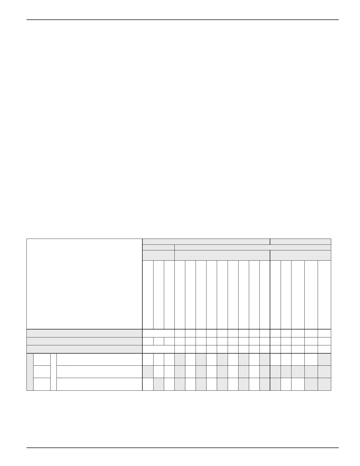
Fill Mode Input/Outputs Chart
C = Chirp on State Entry
F = O
P = Pulsing / Flashing
T = Steady On
MICRO CONTROL BOARD POWER BOARD
INPUTS OUTPUTS
PUSH
BUTTONS
12VDC 115/230VAC
Lock
Unlock
Horn Silence
Inside Red light
Inside Green light
Corner-Vu Red light [CVU RD]
Corner-Vu Green light [CVU GRN]
Leveler-Vu Red light [LVU RD]
Leveler-Vu Green light [L-VU GRN]
Outside Red light [OSR]
Outside Green light [OSG]
Dok-Lok horn [HORN]
Leveler Motor Contactor
[COMBINED POWER UNIT ONLY]
Motor Ouptut #1 [M1/LOCK]
Solenoid #1 (RSOL1 / RAISE)
Solenoid #2 (RSOL2 / DIVERT)
[COMBINED POWER UNIT ONLY]
12VDC power supply ok
TERMINAL BLOCK NO.
Membrane J7.16 J7.17 J12.1 J12.2 J12.3 J12.4 J11.2 J11.1 J7.19 J15.1 J1.4 J7.3 J7.2 J2.1-6
POWER BOARD LEDS
– – – – – – – – – – – – – LD2 LD10 LD9 LD7
MICRO CONTROL BOARD LEDS
LD52 LD17 LD19 LD11 LD13 LD18 LD12 LD49 LD48 LD15 LD42 LD1 LD8 LD6 –
NO.
01.15.14
State/Sequence No.
Fill Mode Sequence – – – T F T F T F P F C F F F F T
01.15.15 Service Motor Up M – – T F T F T F P F C T T T T T
01.15.16 Service Motor Down – M – T F T F T F P F C T F F T T