Pub. No. 8000CLB FEBRUARY 2004 7
PROTECDOR® CL Model 8000CL
9. Remove the curtain shipping band. The curtain will not
unroll because the brake is holding the curtain in position.
10. Using the manual brake release handle, disengage the
brake and slowly lower the curtain until the bottom is even
with the top of the door opening, Figure 11. Release the
manual brake lever to hold the door in this position.
11. Rotate the large limit switch pulley to align the magnet
assembly with the red OPEN limit switch, Figure 12.
12. Install the limit switch belt over the small pulley on the
roller tube and the large pulley on the limit switch
assembly. Loosen the two 3/8" limit switch mounting bolts.
Make sure that the timing belt is seated in the grooves on
both of the pulleys.
13. Pull down slightly on the limit switch mounting plate to
apply tension to the timing belt and tighten the two 3/8"
bolts. In most cases, just the weight of the limit switch
assembly will provide enough tensioning.
14. Slide the 1" conduit fitting into the same bracket that the
3/4" motor conduit is secured to and tighten the lock nut,
Figure 10.
15. Connect and secure all mating wire connectors from the
motor, photoeyes, limit switches, and sensing system.
NOTE: The two photoeye connectors are red in color.
These must not be plugged into any other color
connector.
16. The door ground wire is pre-attached at the factory to the
door frame assembly by using the hex head screw and
star washer attached to the conduit mounting bracket,
Figure 12.
17. Secure all wires clear of moving parts with a wire tie.
18. Pull the manual brake release handle to slowly lower the
door until the curtain is 4" from the floor.
19. Locate the close limit switch adjustment plate. Loosen the
1/4” thumb screw and rotate the limit switch plate until the
black limit switch aligns with the magnet, Figure 12.
Lightly tighten the lock bolt.
NOTE:
The white tipped limit switch deactivates the
photoeye prior to the door fully closing.
ROLLER TUBE INSTALLATION
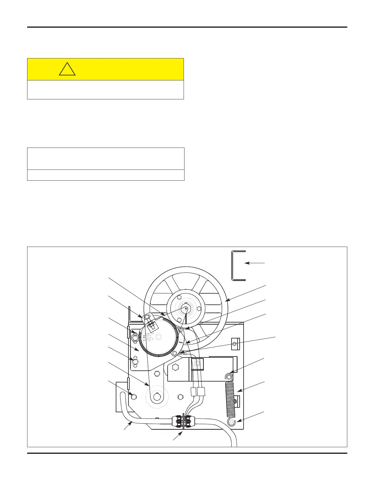
FIGURE 12
VIEW OF A RIGHT-HAND DRIVE
Limit Switch Drive Belt
Open Limit Switch (Red)
Adjustment Slots
Limit Switch Mounting Bolts
Drive Belt
Motor Bolts
Motor Cable
Ground Screw
Anchor Peg
Photoeye Deactivate
Switch (White)
Driven Pulley
Header Channel
Drive Belt Tension Spring
Closed Limit Switch
Adjustment Plate
Closed Limit Switch (Black)
Motor Drive Belt Tensioner
Limit Switch Mounting Plate
Keep hands and loose clothing away from the
pulleys and belts while manually releasing the brake.
CAUTION !!!
!
Do not over tension the limit switch timing belt.
IMPORTANT!!!