6 Pub. No. 8000CLB FEBRUARY 2004
PROTECDOR® CL Model 8000CL
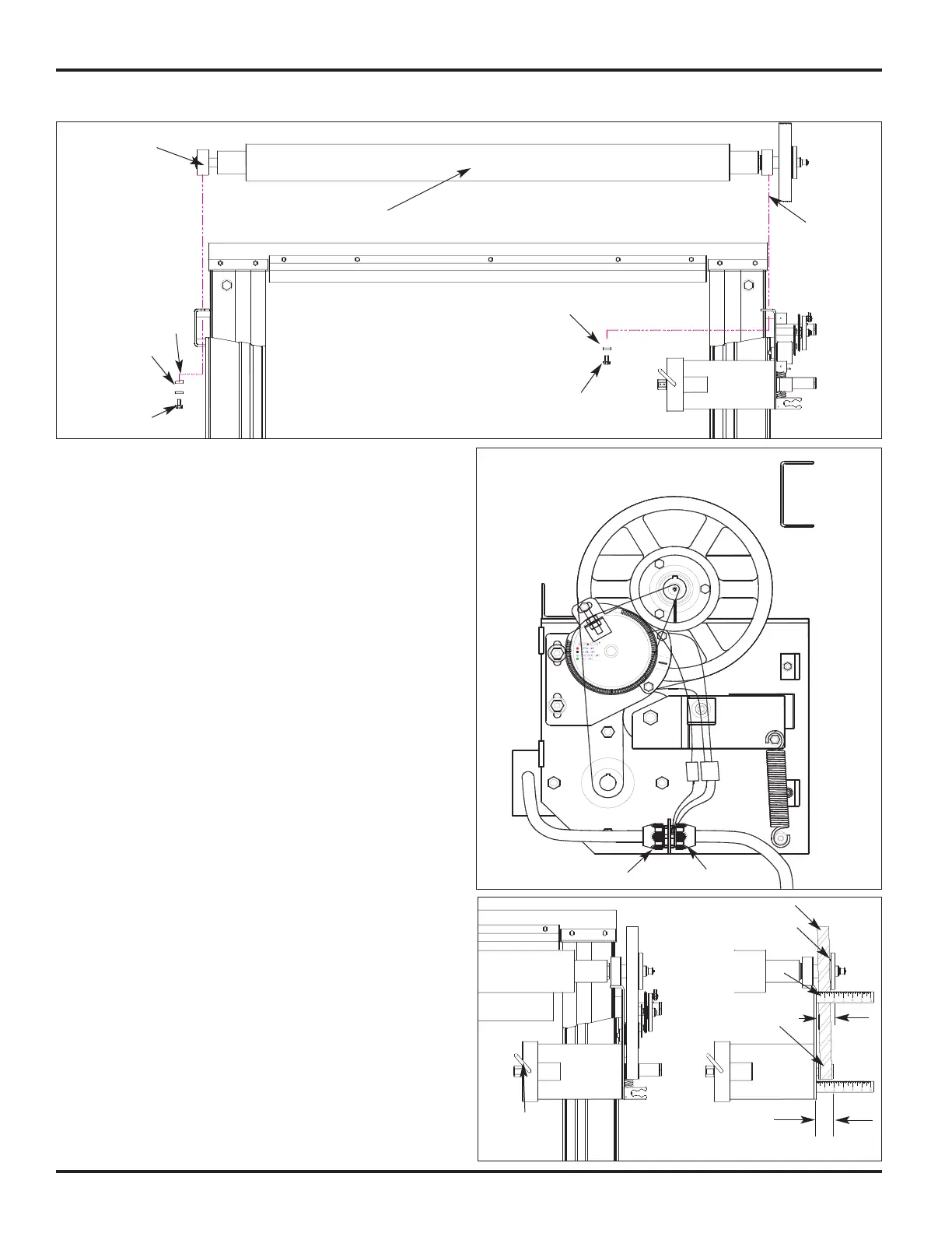
1. Use a lift truck, lift and position the roller tube assembly
above the sideframes, Figure 8.
2. Carefully lower the roller tube assembly into position on
top of the sideframes by aligning the bolt holes in the
pillow blocks and the mounting brackets, Figure 9.
3. Align and fully tighten the drive side roller tube mounting bolts.
NOTE: The non-drive side uses 7/16" x 1 1/4" bolts, flat
washers, and tapered washers; the drive side
uses 7/16" x 1" bolts and lock washers.
4. Align the roller tube mounting bolts and tapered washers
on the non-drive side and fully tighten. If necessary,
loosen the two set screws on the pillow block bearing to
align mounting holes. Tighten the two bearing block set
screws on the non-drive side to 66 to 80 in/lbs. of torque.
5. Using a 12" long straight edge, check to see that the large
pulley is square with the motor mounting plate. Place the
straight edge perpendicularly along the outside face of the
motor mounting plate and measure at the front and back
of the pulley, Figure 11. If these measurements are not
within 1/16", shim behind the drive side sideframe
assembly. Refer to Step 11 on Page 5.
6. Install the drive belt onto the drive pulley on the motor and
then position the belt on the large pulley on the roller tube
assembly, Figures 10 & 11. Make sure that the belt ribs
are fully seated in the grooves of both pulleys.
7. Engage the tensioning system by pulling the loose end of
the tension spring downward and hooking the spring end
over the anchoring peg, Figures 10 & 13. Make sure to
position both of the spring ends (top and bottom) in the
grooves of the nylon bushing.
8. Using a straight edge, measure the distance between the
drive belt and the motor plate at the large pulley and at
the motor pulley. The measurement taken at the motor
pulley must be within 1/32" of the measurement taken at
the large pulley. If an adjustment is required, loosen the
motor pulley set screws and align the motor pulley as
required. Tighten the set screws and recheck the
measurement, Figure 11.
ROLLER TUBE ASSEMBLY / DRIVE BELT
FIGURE 9
Pillow block
bearing w/ set
screws
7/16” x 1-1/4”
Bolt
Flat Washer
Roller tube assembly
Pulley
Tapered Washer
7/16” x 1” Bolt
Lock Washer
FIGURE 10
VIEW OF A RIGHT-HAND DRIVE
3/4”
1”
FIGURE 11
Bottom Edge
Brake
Release
Handle
Drive Belt
Large Driven Pulley
Motor Pulley
with set screws
Straight Edge
“X” =/- 1/32”
“X”