Do you have a question about the Rittal SK 3209 Series and is the answer not in the manual?
Confirmation of conformity with EU Machinery and EMC Directives.
Instructions must be kept with the unit for operating and maintenance personnel.
Explanation of warning, caution, attention, and note symbols.
Mentions assembly and operating instructions as paper documents and liability.
General safety notes for assembly and operation, including specialist training and environmental conditions.
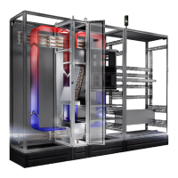
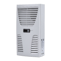
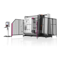
Describes the purpose of heat exchangers for cooling enclosures and protecting components.
Explains the main components: heat exchanger, fan, and magnetic valve.
Details the built-in controllers (Basic or e-Comfort) for setting functions.
Enables bus connection for up to ten units with master-slave functionality.
Covers thermal winding protection, floating contacts for system messages, and leak warning.
Explains condensation formation and its routing via a drain opening.
Details the response to water leakage or pipe breakage.
Describes the function of an optional door limit switch for preventing condensation.
Allows connection of an interface card for higher-level monitoring systems.
Defines correct usage and hazards associated with improper application.
Lists the items included in the packaging unit.
Critical safety warnings for electrical work, lifting, and tool usage during installation.
Guidelines for selecting a suitable installation location, considering temperature and access.
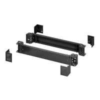
Steps for physically mounting the heat exchanger onto the enclosure.
Instructions on creating the necessary opening in the enclosure roof plate.
Details on attaching the heat exchanger to the prepared enclosure roof.
Guidance on connecting the flexible hose for condensate drainage.
Instructions for connecting the cooling water inlet and return hoses.
Recommendations for cooling water composition to prevent damage and ensure operation.
Techniques for preparing and maintaining water in recooling systems.
Covers all aspects of connecting the unit to the power supply.
Essential notes on complying with regulations and qualified personnel.
Instructions for connecting the optional door limit switch.
Guidance on integrating the unit into an existing potential equalization system for EMC.
Steps for completing the electrical installation and connecting system messages.
Details on operating the unit with the basic controller interface.
Explanation of the display terminal and how to interpret system messages.
Describes the automatic operation of the heat exchanger and controller functions.
Overview of how to navigate and change parameters using the controller buttons.
Explains how to set the temperature and understand the display.
Step-by-step guide to setting the desired enclosure internal temperature.
Procedure for configuring system message evaluation.
Detailed guide to programming and controlling the basic controller unit.
Procedure for resetting stored minimum and maximum internal temperatures.
Details on the system message relay contact and its connection.
Visual guide to the programming sequence for the basic controller.
Information on operating the unit with the advanced e-Comfort controller.
Highlights features like start-up delay, fan monitoring, and master-slave function.
Procedure for activating the test function for cooling operation.
Explains how to navigate and program parameters on the e-Comfort controller.
Details the energy-saving eco-mode function and its activation/deactivation.
Lists and describes all programmable parameters for the e-Comfort controller.
Instructions for networking multiple units using the serial interface.
Visual guide to the programming sequence for the e-Comfort controller.
Explains how to assign system messages to relays for evaluation.
Procedure for configuring master and slave units in a network.
Troubleshooting guide for system messages indicated on the e-Comfort controller.
Outlines general maintenance tasks such as checking dirt levels and cooling membranes.
Instructions for draining the unit for storage, transport, and disposal.
Key technical data for units with Basic controller.
Key technical data for units with e-Comfort controller.
Information on how to identify and order spare parts.
Summary of recommended system water composition to prevent damage.
Graphs showing water resistance versus volumetric flow.
Technical drawings showing the physical dimensions of the unit.
Formal statement declaring conformity with EU directives.
| Brand | Rittal |
|---|---|
| Model | SK 3209 Series |
| Category | Industrial Equipment |
| Language | English |