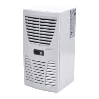
Do you have a question about the Rittal SK 3366. series and is the answer not in the manual?
Details on available documentation sets for the cooling units.
Information regarding the CE declaration of conformity.
Requirements for keeping manual and associated documents.
Explanation of symbols used for safety and notes.
Essential safety guidelines for assembly, operation, and servicing.
Explanation of how the cooling unit dissipates heat and its components.
Details the compression refrigeration system cycle.
Overview of Basic and Comfort controller options.
Master-slave connection for multiple cooling units.
Details safety features like pressure switches and thermal winding shields.
How condensation is handled and evaporated.
Filter mat types, function, and monitoring.
Functionality and notes for the optional door limit switch.
Guidelines for selecting an optimal location for the cooling unit.
Checks and recommendations before starting assembly.
Options for external, partial, and full internal mounting.
Instructions for connecting the condensate drain hose.
Important considerations for electrical connections and safety.
Step-by-step guidance for electrical wiring.
Arranging components for proper airflow and avoiding condensation.
Steps for preparing the enclosure panel for unit mounting.
Attaching the cooling unit externally to the enclosure.
Mounting the unit partially inside the enclosure.
Integrating the cooling unit fully inside the enclosure.
Connecting the drain hose for specific models.
Required voltage, frequency, and connection requirements.
Protecting against overvoltage and supply line load.
Specific electrical connection needs for three-phase units.
Connecting and using the optional door limit switch.
Adhering to flicker emission limits.
Connecting to the potential equalization system.
Connecting multiple units in a master-slave configuration.
Using interface card for system monitoring and integration.
Diagram showing a typical master-slave network setup.
Completing electrical installation and power supply connection.
Wiring diagram for specific cooling unit models.
Wiring diagram for specific cooling unit models.
Wiring diagram for specific cooling unit models.
Wiring diagram for specific cooling unit models.
Wiring diagram for specific cooling unit models.
Wiring diagram for specific cooling unit models.
Wiring diagram for specific cooling unit models.
Wiring diagram for specific cooling unit models.
Wiring diagram for specific cooling unit models.
Wiring diagram for specific cooling unit models.
Wiring diagram for specific cooling unit models.
Wiring diagram for specific cooling unit models.
Wiring diagram for specific cooling unit models.
Explanation of symbols used in the electrical wiring diagrams.
Final steps after assembly, including filter installation.
Procedures for installing filter mats in the cooling unit.
Steps for attaching the display and louvred grille.
Configuration for the filter mat monitoring function.
How to operate the cooling unit using the Basic controller.
Supported voltages, functions, and display features.
Understanding the LED indicators for status and errors.
Detailed table explaining LED status, causes, and solutions.
How to activate the test function for the Basic controller.
Instructions for adjusting the temperature setpoint.
Procedure for resetting the controller after an alarm.
How to operate the cooling unit using the Comfort controller.
Supported voltages, functions, and master-slave capabilities.
Activating the test function for the Comfort controller.
Overview of parameter adjustment and programming.
Details on adjustable parameters and their settings.
Visual guide to programming parameters using buttons.
Listing and explanation of system messages for evaluation.
How system messages are linked to relay outputs.
Configuring identifiers for master and slave cooling units.
Interpreting system messages and required reset actions.
Table of system messages, causes, and rectification measures.
Procedure to reset the controller after specific faults.
Cleaning the unit's components using compressed air.
Cleaning instructions specific to SK 3328, 3329, 3332 series.
Detailed specifications for various models.
Continued detailed specifications for various models.
Continued detailed specifications for various models.
Exploded view showing spare parts for SK 3302.xxx models.
Exploded view showing spare parts for SK 3302.3xx models.
Exploded view showing spare parts for SK 3303.xxx and SK 3361.xxx.
Exploded view showing spare parts for SK 3304.xxx and SK 3305.xxx.
Exploded view showing spare parts for SK 3328.xxx and SK 3329.xxx.
Exploded view showing spare parts for SK 3332.xxx models.
Exploded view showing spare parts for SK 3366.xxx and SK 3377.xxx.
Information required when ordering spare parts.
Technical drawings of external mounting dimensions.
Technical drawings of external mounting dimensions.
Technical drawings for partial internal mounting.
Technical drawings for full internal mounting.
| Brand | Rittal |
|---|---|
| Model | SK 3366. series |
| Category | Air Conditioner |
| Language | English |


 Loading...