Do you have a question about the Rittal SK 3383.xxx and is the answer not in the manual?
Details two sets of instructions: paper document and PDF on CD-ROM for unit assembly and operation.
States that the declaration of conformity is supplied as a separate document with the unit.
Emphasizes instructions are integral product parts, must be given to plant operator and kept accessible.
Explains symbols for instructed actions and safety warnings: Danger, Caution, and Note.
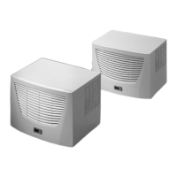
Explains cooling units dissipate heat by cooling enclosure air using a compression refrigeration system.
Describes the controller for setting unit functions, including display and extended functions.
Details the serial interface X2 for bus connection of up to ten cooling units in a network.
Covers pressure-operated switch, icing prevention, thermal winding shields, and floating contacts.
Explains condensation formation and automatic electrical evaporation using PTC technology.
Discusses filter options (PU foam, metal) and the filter mat monitor function.
Details operation with a door limit switch to prevent condensation inside the enclosure.
Describes interface for higher-level monitoring systems via a 9-pole SUB-D connector.
Defines intended use and user responsibility for safe operation and adherence to regulations.
Lists the items included in the delivery package of the cooling unit.
Guidelines for selecting enclosure location, ventilation, temperature, and site conditions.
General checks for packaging damage, enclosure sealing, and avoiding condensation during assembly.
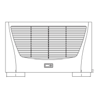
Instructions for mounting the cooling unit on the enclosure roof using templates and sealing frames.
How to connect the condensate discharge hose, ensuring proper routing and gradient.
Important considerations for electrical installation, including connection data, pre-fuse, and overvoltage protection.
Procedures for bus connection, serial interface connection, and power supply installation.
Steps for installing filter media, connecting the display, and attaching the louvred grille.
How to operate the unit using the controller, including test mode, programming, and eco-mode.
Details editable parameters like setpoint, filter monitoring, temperature conversion, and error messages.
Visual guide showing the sequence of button presses for parameter programming.
Explains system messages shown on display and their evaluation via relays.
How to configure master and slave units for networked operation and assign identifiers.
How system messages are indicated by numbers and require resetting the controller.
Procedure to reset the controller after specific faults (A03, A06, A07) occur.
Overview of the maintenance-free system, cleaning external air circuits, and maintenance intervals.
Provides detailed dimensional drawings for unit installation and cut-out dimensions.
| Type | Refrigerator |
|---|---|
| Model | SK 3383.xxx |
| Rated operating voltage | 230 V AC |
| Voltage | 230 V |
| Frequency | 50/60 Hz |
| Refrigerant | R134a |