RCMR Pag. 39 Rev. 02 02 13
UK
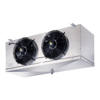
Figure 9– Terminal boards in the shunt box.
1. insert a spindle on the specific opening (near the middle of the terminal board);
2. the blade of the spindle keeps the spring open, allowing the operator to introduce the conductor;
3. insert the conductor with the end peeled off or equipped with a crimped terminal;
4. pull out the spindle. the conductor is thus safely fastened.
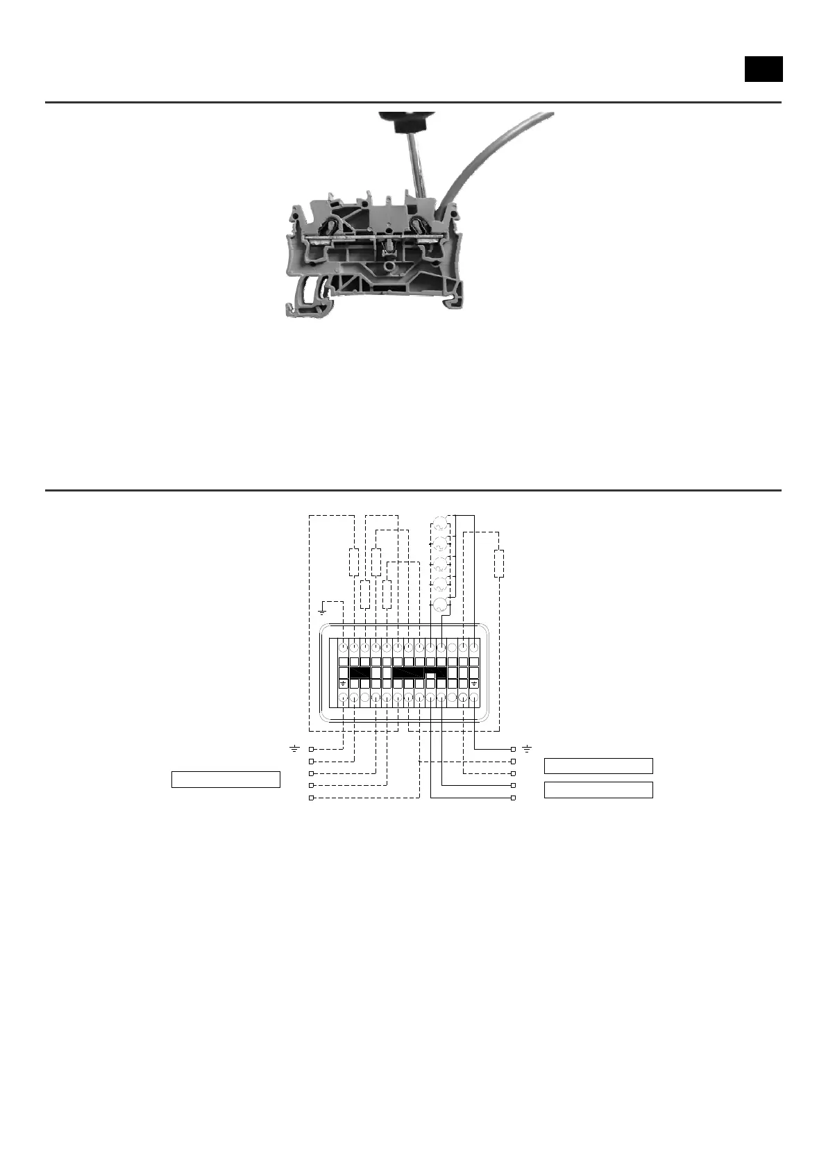
4.3.5.1 Wiring of RCMR Ø350
All the models have fan motors powered with a voltage of 230V/1Ph/50-60Hz; defrosting heaters are present on the ED models,
arranged to be powered with 400V/3Ph/50-60Hz (see Figure 10). If you want to power the heaters with a voltage of 230V/1Ph/50-
60Hz, modify the connection as shown in Figure 11.
Figure 10 – Wiring diagram RCMR Ø350 with defrosting heaters powered with 400V/3Ph/50-60Hz.
1
R
2
R
3
R
4
R
M2
M4
M3
M5
M1
1
1
23NNN
4N
7 5
5
R
N
L
N
L3
L2
L1
N
L
400V/3Ph/50-60Hz
230V/1Ph/50-60Hz
230V/1Ph/50-60Hz