RCMR Pag. 40 Rev. 02 02 13
UK
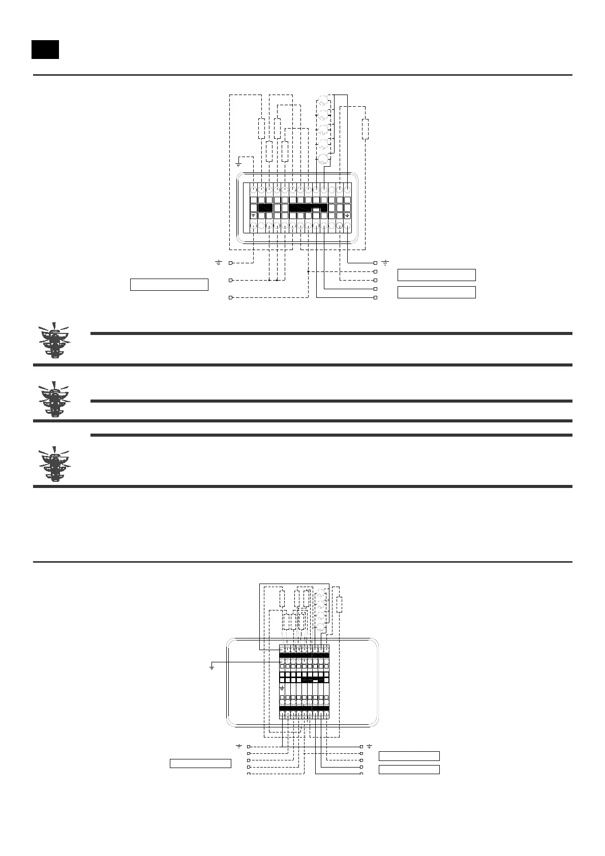
Figure 11 – Wiring diagram RCMR Ø350 with defrosting heaters powered with 230V/1Ph/50-60Hz.
1
R
2
R
3
R
4
R
M2
M4
M3
M5
M1
112
3N
N
N
4
N
7 5
5
R
N
L
N
L
N
L
230V/1Ph/50-60Hz
230V/1Ph/50-60Hz
230V/1Ph/50-60Hz
ATTENTION: the defrost heaters are only included in the ED version (version with electrical defrost Figure 10-11 see R1,
R2 ,R3, and R4).The drainage heater is supplied as optional (Figure 10- 11 see R5)
To make the wires pass, use the side openings that are already arranged.
ATTENTION
:
Rigorously follow the wiring diagrams reported above to avoid damages.
ATTENTION: Rigorously follow the wiring diagrams reported above to avoid damages to the motor. The motors
themselves are equipped with a protective, automatic restart system. If you intend to use a system to adjust
the number of fan motor revs, make sure that it is compatible with the fan motor; incompatible systems may
generate noise and cause damages.
4.3.5.2 Wiring of RCMR Ø450
All the models have fan motors powered with a voltage of 230V/1Ph/50-60Hz; defrosting heaters are present on the ED models,
arranged to be powered with 400V/3Ph/50-60Hz (see Figure 12). If you want to power the heaters with a voltage of 230V/1Ph/50-
60Hz, modify the connection as shown in Figure 13.
Figure 12 – Wiring diagram RCMR Ø450 with defrosting heaters powered with 400V/3Ph/50-60Hz.
M2
M4
M3
M1
123NN4N
5
1
R
3
R
5
R
7
R
2
R
4
R
6
R
L
N
L
N
230V/1Ph/50-60Hz
230V/1Ph/50-60Hz
N
L3
L2
L1
400V/3Ph/50-60Hz