Check for parts online at www.HuntRiversEdge.com or call 800-450-EDGE (3343) M-F 8-5
7
Operator's Manual
RETREAT 1-MAN Ladder Stand
ASSEMBLY INSTRUCTIONS
IMPORTANT ASSEMBLY TIP:
Do not tighten any nut and bolt combinations completely
until all parts are assembled together! Finger tighten plus
one turn of a wrench only! This will temporarily hold the
lock- nut on the bolt while helping alignment of all parts!
After all parts are assembled together, all nut and bolt combi-
nations must be completely tightened.
All assembly must be done in this order at ground
level before uprighting.
Do not remove labels/warnings from product, they are
there for your safety.
Recommended for adult use only.
FIGURE 1
FIGURE 2
NOTE: When selecting a tree to install the treestand in, never
use a treestand on a dead leaning, diseased or loose barked
tree, or a utility pole. Always avoid electrical power lines.
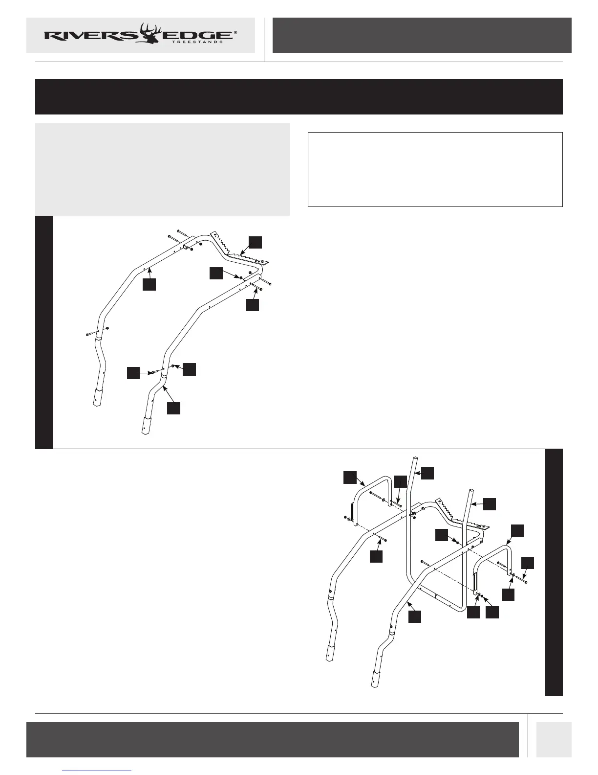
1. Join the two seat side rails (9) and two ared platform
rails (8) as shown in FIGURE 1. Secure parts together with two
1/4-20 X 1-1/2 IN bolts (33) and two 1/4-20 nuts (36).
2. Assemble the tree blade (18) using four 1/4 -20 X 2-1/2 IN bolts
(32) and four 1/4-20 nuts (36) as shown in FIGURE 1.
9
3. Attach the front of the armrests: left (11) and right (12) to the
outer edge of the seat side rails (9), using two 1/4 -20 X 2-1/4
IN bolts (34), two yellow washers (23) and two 1/4-20 nuts (36).
Be sure the armrest orientation is correct. SEE FIGURE 2.
4. Connect the rear of the armrests (11 & 12) to the seat side rails (9) and
rear seat supports: left (19) and right (14) using two 1/4-20 X 3-1/4
IN bolts (35), two yellow washers (23) and two 1/4-20 nuts (36).
During this step the two M6 x 60 MM carriage bolts (30) must
be inserted into the holes in the armrests (11 & 12) or they will
not be able to be installed after the armrests have been assem-
bled. SEE FIGURE 2.
32
18
36
36
33
8
12
30
34
14
36
19
9
23 36
23
35
11